Container > NHN Kubernetes Service (NKS) > User Guide
Cluster
Cluster refers to a group of instances that comprise user's Kubernetes.
Kubernetes Version Support Policy
NKS's Kubernetes version support policy is as follows.
- Support for the latest Kubernetes version
- NKS continuously delivers the latest Kubernetes version to ensure that your cluster is up to date.
- You can create a cluster with a new version or upgrade an existing cluster to a new version.
- Createable version
- The number of Kubernetes versions that allow you to create clusters remains at 4.
- Therefore, when a new available version is added, the oldest available version is removed from the available version list.
- Serviceable version
- Clusters using end-of-service versions are not guaranteed to work with new features in NKS.
- You can upgrade the Kubernetes version of your cluster with the cluster version upgrade feature in NKS.
- The number of Kubernetes versions that can be serviced remains at five.
- So when a new version is added to the createable versions, the lowest version among the serviceable versions is removed.
For each Kubernetes version, here's when you can expect to see additions/deletions to the createable versions and when versions are listed as end of service. (Note that this table is current as of September 26, 2023, and the version names of createable versions and when they are provided are subject to change due to our internal circumstances)
| Version | Add to Createable Versions | Remove from Createable Versions | End of Service Support |
|---|---|---|---|
| v1.22.3 | 2022. 01. | 2023. 05. | 2023. 08. |
| v1.23.3 | 2022. 03. | 2023. 08. | 2024. 02. |
| v1.24.3 | 2022. 09. | 2024. 02. | 2024. 05.(Scheduled) |
| v1.25.4 | 2023. 01. | 2024. 05.(Scheduled) | 2024. 08.(Scheduled) |
| v1.26.3 | 2023. 05. | 2024. 08.(Scheduled) | 2025. 02.(Scheduled) |
| v1.27.3 | 2023. 08. | 2025. 02.(Scheduled) | 2025. 05.(Scheduled) |
| v1.28.3 | 2024. 02. | 2025. 05.(Scheduled) | 2025. 08.(Scheduled) |
| v1.29.x | 2024. 05.(Scheduled) | 2025. 08.(Scheduled) | 2025. 11.(Scheduled) |
Creating Clusters
To use NHN Kubernetes Service (NKS), you must create clusters first.
[Caution] Setting up permissions to use clusters
To create a cluster, the user must have Infrastructure ADMIN or Infrastructure LoadBalancer ADMIN permissions of basic infrastructure services for the project. Only with the permissions, the user can normally create and operate clusters running on basic infrastructure services. It is totally possible to add one of the two permissions when the other is already acquired. To learn more about setting up permissions, see Manage Project Members. If there is some change to the permissions (permissions added or deleted) that were set up when creating a cluster, some features of the cluster may be restricted. For more information, see Change Cluster OWNER.
Go to Container > NHN Kubernetes Service(NKS) and click Create Cluster and a page for creating clusters shows up. The following items are required to create a cluster.
| Item | Description |
|---|---|
| Cluster Name | Name of a Kubernetes cluster. It is limited to 20 characters, and only lowercase English letters, numbers, and '-' can be entered. It must start with a lowercase letter and end with a lowercase letter or number. RFC 4122 compliant UUID formats cannot be used. |
| Kubernetes Version | Kubernetes version to use |
| VPC | VPC network to be attached to clusters |
| Subnet | Subnet to be associated with instances that comprise a cluster, among those defined in VPC |
| NCR Service Gateway | NCR Type Service Gateway (but only if your subnet is not connected to the internet gateway |
| OBS Service Gateway | OBS Type Service Gateway (but only if your subnet is not connected to the internet gateway |
| K8s Service Network | Service object CIDR for a cluster |
| Pod Network | Pod network for a cluster |
| Pod Subnet Size | Pod subnet size for a cluster |
| Kubernetes API endpoint | Public: Endpoint assigned with the domain address and associated with a floating IP Private: Endpoint set to an internal network address |
| Enhanced Security Rule | Create only required security rules when creating a worker node security group. See C True: Create only required security rules False: Create required security rules and security rules that allow all ports |
| Image | Images for instances comprising a cluster |
| Availability Zone | Area to create a default node group instance |
| Flavor | Instance specifications for a default node group |
| Node Count | Number of instances for a default node group |
| Key Pair | Key pair to access default node group |
| Block Storage Type | Type of block storage for a default node group instance |
| Block Storage Size | Size of block storage for a default node group instance |
| Additional Network | Additional network and subnet to create in a default worker node group |
[Caution] For CIDRs of VPC network subnet, K8s service network and pod network, the following constraints must be avoided. - CIDR cannot overlap with the link-local address band (169.254.0.0/16). - CIDR cannot overlap with bands of the VPC network subnet or additional network subnets, pod network, and K8s service network. - CIDR cannot overlap with the IP band (198.18.0.0/19) being used inside the NKS. - You cannot enter a CIDR block greater than /24. (The following CIDR blocks are not available: /26, /30). - For clusters of v1.23.3 or earlier, they cannot overlap with BIP (bridged IP range) (172.17.0.0/16).
You should not delete the service gateway that you set up when you created the cluster. - If the selected subnet is not connected to an internet gateway, you need to set up NCR service gateway and OBS service gateway. - These two service gateways are used to get the images/binaries required for NKS cluster configuration and basic features. - If you delete the service gateway that was set up when the cluster was created, the cluster will not work properly.
You should not change the Internet gateway connectivity for the subnet you set when you created the cluster. - The registry to receive the image/binary depends on whether the subnet you set up when creating the cluster is connected to the internet gateway or not. - If the subnet's Internet gateway connectivity changes after the cluster is created, the cluster will not work properly because it cannot connect to the set registry.
[Maximum number of nodes that can be created] The maximum number of nodes that can be created when creating a cluster is determined by the pod network, pod subnet size settings. Calculation: 2^(Pod Subnet Size - Host Bits in Pod Network) - 3 Example: - Pod subnet size = 24 - Pod network = 10.100.0.0/16 - Calculation: 2 ^ (24 - 16) - 3 = up to 253 nodes can be created
[Maximum number of IPs that can be assigned to the Pod for each node] The maximum number of IPs that can be used on a single node is determined by the Pods subnet size setting. Calculation: 2^(32 - pods_network_subnet) - 2 Example: - Pod subnet size = 24 - Calculation: 2 ^ (32 - 24) - 2 = up to 254 IPs available
[Maximum number of IPs that can be assigned to Pods in the cluster] Calculation: Maximum number of IPs that can be assigned to a Pod for each node * Maximum number of nodes that can be created Example: - Pod subnet size = 24 - Pod network = 10.100.0.0/16 - Calculate: 254 (maximum number of IPs that can be assigned to a Pod for each node) * 253 (maximum number of nodes that can be created) = 64,262 IPs available at most
NHN Kubernetes Service (NKS) supports several versions of Kubernetes. Some features may be restricted depending on the version.
| Version | Creating a new cluster | Using the created cluster |
|---|---|---|
| v1.17.6 | Unavailable | Available |
| v1.18.19 | Unavailable | Available |
| v1.19.13 | Unavailable | Available |
| v1.20.12 | Unavailable | Available |
| v1.21.6 | Unavailable | Available |
| v1.22.3 | Unavailable | Available |
| v1.23.3 | Unavailable | Available |
| v1.24.3 | Unavailable | Available |
| v1.25.4 | Available | Available |
| v1.26.3 | Available | Available |
| v1.27.3 | Available | Available |
| v1.28.3 | Available | Available |
NHN Kubernetes Service (NKS) provides different types of Container Network Interface (CNI) according its version. After 31 March 2023, CNI is created with Calico when creating a cluster with version 1.24.3 or higher. Network mode of Flannel and Calico CNI all operate in VXLAN method.
| Version | CNI Type and Version Installed when creating Cluster | CNI Change Available |
|---|---|---|
| v1.17.6 | Flannel v0.12.0 | Unavailable |
| v1.18.19 | Flannel v0.12.0 | Unavailable |
| v1.19.13 | Flannel v0.14.0 | Unavailable |
| v1.20.12 | Flannel v0.14.0 | Unavailable |
| v1.21.6 | Flannel v0.14.0 | Unavailable |
| v1.22.3 | Flannel v0.14.0 | Unavailable |
| v1.23.3 | Flannel v0.14.0 | Unavailable |
| v1.24.3 | Flannel v0.14.0 or Calico v3.24.1 1 | Conditionally Available |
| v1.25.4 | Flannel v0.14.0 or Calico v3.24.1 1 | Conditionally Available |
| v1.26.3 | Flannel v0.14.0 or Calico v3.24.1 1 | Conditionally Available |
| v1.27.3 | Calico v3.24.1 | Unavailable |
| v1.28.3 | Calico v3.24.1 | Unavailable |
Notes
- 1: Flannel is installed in clusters created before 31 March 2023. For clusters of v1.24.3 or higher created after that date, Calico is installed.
- 2: CNI change is only supported on clusters of v1.24.3 or higher, and currently changing from Flannel to Calico is only supported.
Required Security Rules for Cluster Worker Nodes
| Direction | IP protocol | Port range | Ether | Remote | Description | Considerations |
|---|---|---|---|---|---|---|
| ingress | TCP | 10250 | IPv4 | Worker node | kubelet port, direction: metrics-server(worker node) -> kubelet(worker node) | |
| ingress | TCP | 10250 | IPv4 | Master node | kubelet port, direction: kube-apiserver(NKS Control plane) -> kubelet(worker node) | |
| ingress | TCP | 5473 | IPv4 | Worker node | calico-typha port, direction: calico-node(worker node) -> calico-typha(worker node) | Created when CNI is calico |
| ingress | UDP | 8472 | IPv4 | Worker node | flannel vxlan overlay network port, direction: pod(worker node) -> pod(worker node) | Created when CNI is flannel |
| ingress | UDP | 8472 | IPv4 | Worker node | flannel vxlan overlay network port, direction: pod(NKS Control plane) -> pod(worker node) | Created when CNI is flannel |
| ingress | UDP | 4789 | IPv4 | Worker node | calico-node vxlan overlay network port, direction: pod(worker node) -> pod(worker node) | Created when CNI is calico |
| ingress | UDP | 4789 | IPv4 | Master node | Calico-node vxlan overlay network port, direction: pod(NKS Control plane) -> pod(worker node) | Created when CNI is calico |
| egress | TCP | 2379 | IPv4 | Master node | etcd port, direction: calico-kube-controller(worker node) -> etcd(NKS Control plane) | |
| egress | TCP | 6443 | IPv4 | Kubernetes API endpoint | kube-apiserver port, direction: kubelet, kube-proxy(worker node) -> kube-apiserver(NKS Control plane) | |
| egress | TCP | 6443 | IPv4 | Master node | kube-apiserver port, direction: default kubernetes service(worker node) -> kube-apiserver(NKS Control plane) | |
| egress | TCP | 5473 | IPv4 | Worker node | Created when CNI is calico, calico-typha port, direction: calico-node(worker node) -> calico-typha(worker node) | |
| egress | TCP | 53 | IPv4 | Worker node | DNS port, direction: worker node -> external | |
| egress | TCP | 443 | IPv4 | Allow all | HTTPS port, direction: worker node -> external | |
| egress | TCP | 80 | IPv4 | Allow all | HTTP port, direction: worker node -> external | |
| egress | UDP | 8472 | IPv4 | Worker node | flannel vxlan overlay network port, direction: pod(worker node) -> pod(worker node) | Created when CNI is flannel |
| egress | UDP | 8472 | IPv4 | Master node | flannel vxlan overlay network port, direction: pod (worker node) -> pod (NKS Control plane) | Created when CNI is flannel |
| egress | UDP | 4789 | IPv4 | Worker node | calico-node vxlan overlay network port, direction: pod(worker node) -> pod(worker node) | Created when CNI is calico |
| egress | UDP | 4789 | IPv4 | Master node | calico-node vxlan overlay network port, direction: pod(worker node) -> pod(NKS Control plane) | Created when CNI is calico |
| egress | UDP | 53 | IPv4 | Allow all | DNS port, direction: worker node -> external |
When using enhanced security rules, the NodePort type of service and the ports used by the NHN Cloud NAS service are not added to the security rules. You need to set the following security rules as needed.
| Direction | IP protocol | Port range | Ether | Remote | Description |
|---|---|---|---|---|---|
| ingress, egress | TCP | 30000 - 32767 | IPv4 | Allow all | NKS service object NodePort, direction: external -> worker node |
| egress | TCP | 2049 | IPv4 | NHN Cloud NAS service IP address | RPC NFS port of csi-nfs-node, direction: csi-nfs-node(worker node) -> NHN Cloud NAS service |
| egress | TCP | 111 | IPv4 | NHN Cloud NAS service IP address | rpc portmapper port of csi-nfs-node, direction: csi-nfs-node(worker node) -> NHN Cloud NAS service |
| egress | TCP | 635 | IPv4 | NHN Cloud NAS service IP address | rpc mountd port of csi-nfs-node, direction: csi-nfs-node(worker node) -> NHN Cloud NAS service |
If you don't use enhanced security rules, additional security rules are created for services of type NodePort and for external network communication.
| Direction | IP protocol | Port range | Ether | Remote | Description |
|---|---|---|---|---|---|
| ingress | TCP | 1 - 65535 | IPv4 | Worker node | All ports, direction: worker node -> worker node |
| ingress | TCP | 1 - 65535 | IPv4 | Master node | All ports, direction: NKS Control plane -> worker node |
| ingress | TCP | 30000 - 32767 | IPv4 | Allow all | NKS service object NodePort, direction: external -> worker node |
| ingress | UDP | 1 - 65535 | IPv4 | Worker node | All ports, direction: worker node -> worker node |
| ingress | UDP | 1 - 65535 | IPv4 | Master node | All ports, direction: NKS Control plane -> worker node |
| egress | Random | 1 - 65535 | IPv4 | Allow all | All ports, direction: worker node - > external |
| egress | Random | 1 - 65535 | IPv6 | Allow all | All ports, direction: worker node - > external |
Enter information as required and click Create Cluster, and a cluster begins to be created. You can check the status from the list of clusters. It takes about 10 minutes to create; more time may be required depending on the cluster configuration.
Querying Clusters
A newly created cluster can be found in the Container > NHN Kubernetes Service (NKS) page. Select a cluster and the information is displayed at the bottom.
| Item | Description |
|---|---|
| Cluster Name | Cluster name |
| Node Count | Total number of worker nodes in the cluster |
| Kubernetes Version | Kubernetes version information |
| kubeconfig file | Button to download the kubeconfig file to control the cluster |
| Task Status | Task status for the command to the cluster |
| k8s API status | Behavioral status of Kubernetes API endpoints |
| k8s Node Status | Status of Kubernetes Node resources |
The meaning of each icon of the task status is as follows.
| Icon | Meaning |
|---|---|
| Green solid icon | Normal end of task |
| Circular rotation icon | Task in progress |
| Red solid icon | Task failed |
| Gray solid icon | Cluster unavailable |
The meaning of each icon in the k8s API status is as follows:
| Icon | Meaning |
|---|---|
| Green solid icon | Working properly |
| Yellow solid icon | Information is not accurate because it nears expiration (5 minutes) |
| Red solid icon | Kubernetes API endpoint is not working properly or information expired |
The meaning of each icon in k8s Node status is as follows.
| Icon | Meaning |
|---|---|
| Green solid icon | All nodes in the cluster are in the Ready state |
| Yellow solid icon | Kubernetes API endpoints are not working properly or there are nodes in NotReady in the cluster |
| Red solid icon | All nodes in cluster are in NotReady |
When you select a cluster, cluster information appears at the bottom.
| Item | Description |
|---|---|
| Cluster Name | Name and ID of Kubernetes Cluster |
| Node Count | Number of instances of all nodes comprising a cluster |
| Kubernetes Version | Kubernetes version in service |
| CNI | Kubernetes CNI type in service |
| K8s Service Network | CIDR of the cluster'service object |
| Pod Network | Kubernetes pod network in service |
| Pod Subnet Size | Kubernetes pod subnet size in service |
| VPC | VPC network attached to cluster |
| Subnet | Subnet associated to a node instance comprising a cluster |
| API Endpoint | URI of API endpoint to access cluster for operation |
| Configuration File | Download button of configuration file required to access cluster for operation |
Deleting Clusters
Select a cluster to delete, and click Delete Clusters and it is deleted. It takes about 5 minutes to delete. More time may be required depending on the cluster status.
Change Cluster OWNER
[Notes] The cluster OWNER is set to the user who created the cluster, but can be changed to other user when required.
The cluster operates based on the OWNER permission set when it is created. The permission is used in integrating with Kubernetes and NHN Cloud basic infrastructure services. Basic infrastructure services used by Kubernetes are as follows.
| Basic Infrastructure Service | Kubernetes Integration |
|---|---|
| Compute | Use Instance service when scaling out or in worker nodes through Kubernetes Cluster Auto Scaler |
| Network | Use Load Balancer and Floating IP services when creating Kubernetes Load Balancer service. |
| Storage | Use Block Storage service when creating Kubernetes Persistent Volume |
If any of the following situations occur during operation, basic infrastructure services cannot be used in Kubernetes.
| Situation | Cause |
|---|---|
| Cluster OWNER departure from the project | Project member removal due to cluster OWNER resignation or manual project member removal |
| Change to cluster OWNER permissions | Permissions added or deleted after the cluster is created |
When there is a problem in operating clusters and the clusters cannot be normalized through member and permission setup due to the above reasons, you can perform normalization by changing the cluster OWNER in the NKS console. How to change the cluster OWNER is as follows.
[Notes] The user who changes the cluster OWNER in the console becomes a new cluster OWNER. The cluster after changing the cluster OWNER operates based on the new OWNER permission.
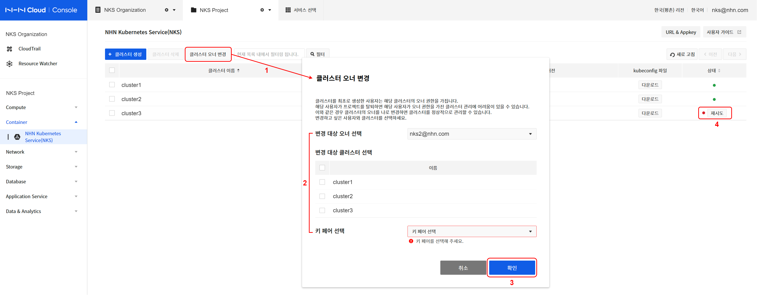
- Click Change Cluster Owner.
- Specify an owner and cluster to change.
- Specify the current owner to choose the cluster to change.
- Select a cluster to change from the listed clusters.
- Specify a key pair to use when creating a new worker node.
- Click Confirm to continue to change the owner.
- Check the status of the cluster to be changed.
- Check the progress of the task for the cluster specified from the listed clusters in the NKS console.
- The status of cluster where changing OWNER is in progress is HANDOVER_IN_PROGRESS, and when the change completes, the status turns to HANDOVER_COMPLETE.
- All node groups under the cluster also turn to the HANDOVER_* status.
- When there is a problem with the change, the status is converted to HANDOVER_FAILED, and it is not allowed to change cluster configuration until normalization completes.
- In this status, the Retry button is shown next to the status icon.
- To normalize the cluster status, click Retry and specifiy a key pair and click Confirm.
[Caution] Change cluster OWNER and key pair
Key pair resources of NHN Cloud basic infrastructure services are dependent on specific users and cannot be shared with other users. (separate from the PEM file downloaded after generating the key pair in the NHN Cloud console) Therefore, the key pair resource specified when creating the cluster must also be newly designated to belong to the new OWNER when the cluster OWNER is changed.
You can connect to the worker nodes (instances) created after changing the cluster OWNER using the newly specified key pair (PEM file). However, you still need the key pair (PEM file) of the existing OWNER to connect to the worker nodes created before the OWNER change. Therefore, even if the OWNER is changed, the existing key pair (PEM file) must be well managed at the project manager level.
Node Group
A node group is comprised of worker node instances that comprise a Kubernetes.
Querying Node Groups
Click a cluster name on the list to find the list of node groups. Select a node group and the brief information shows at the bottom.
| Item | Description |
|---|---|
| Node Group Name | Name of the node group |
| Node Count | The number of nodes in a node group |
| Kubernetes Version | Kubernetes version information applied to the node group |
| Availability Zone | Availability zone information applied to node groups |
| Flavor | Node group instance type |
| Image Type | Node group image type |
| Task Status | Task status for command to the node group |
| k8s Node Status | Status of Kubernetes Node resources belonging to a node group |
The meaning of each icon of the task status is as follows.
| Icon | Meaning |
|---|---|
| Green solid icon | Normal end of task |
| Circular rotation icon | Task in progress |
| Red solid icon | Task failed |
| Gray solid icon | Clusters and node groups unavailable |
The meaning of each icon of k8s Node status is as follows.
| Icon | Meaning |
|---|---|
| Green solid icon | All nodes in the node group are in the Ready state |
| Yellow solid icon | The Kubernetes API endpoint is not working properly or there are nodes in the NotReady status in the node group |
| Red solid icon | All nodes in the node group are in the NotReady status |
When you select a node group, node group information appears at the bottom.
- Basic Information On the Basic Information tab, you can check the following:
| Item | Description |
|---|---|
| Node Group Name | Name and ID of a node group |
| Cluster Name | Name and ID of a cluster to which a node group is included |
| Kubernetes Version | Kubernetes version in service |
| Availability Zone | Area in which a node group instance is created |
| Flavor | Specifications of a node group instance |
| Image Type | Type of image for a node group instance |
| Block Storage Size | Size of block storage for a node group instance |
| Created Date | Time when node group was created |
| Modified Date | Last time when node group was modified |
- List of Nodes Find the list of instances comprising a node group from the List of Nodes tab.
Creating Node Groups
Along with a new cluster, a default node group is created, but more node groups can be created depending on the needs. If higher specifications are required to run a container, or more worker node instances are required to scale out, node groups may be additionally created. Click Create Node Groups from the page of node group list, and the page of creating a node group shows up. The following items are required to create a node group:
| Item | Description |
|---|---|
| Availability Zone | Area to create instances comprising a cluster |
| Node Group Name | Name of an additional node group. It is limited to 20 characters, and only lowercase English letters, numbers, and '-' can be entered. It must start with a lowercase letter and end with a lowercase letter or number. RFC 4122 compliant UUID formats cannot be used. |
| Flavor | Specifications of an instance for additional node group |
| Node Count | Number of instances for additional node group |
| Key Pair | Key pair to access additional node group |
| Block Storage Type | Type of block storage of instance for additional node group |
| Block Storage Size | Size of block storage of instance for additional node group |
| Additional Network | Additional network and subnet to create in a default worker node group |
Enter information as required and click Create Node Groups, and a node group begins to be created. You may check status from the list of node groups. It takes about 5 minutes to create; more time may be required depending on the node group setting.
[Caution] Only the user who created the cluster can create node groups.
Deleting Node Groups
Select a node group to delete from the list of node groups, and click Delete Node Groups and it is deleted. It takes about 5 minutes to delete a node group; more time may be required depending on the node group status.
Adding node to node group
Nodes can be added to operating node groups. The current list of nodes will appear upon clicking the node list tab on the node group information query page. Nodes can be added by selecting the Add Node button and entering the number of nodes you want.
[Caution] Nodes cannot be manually added to node groups on which autoscaler is enabled.
Deleting node from node group
Nodes can be deleted from operating node groups. The current list of nodes will appear upon clicking the node list tab on the node group information query page. A confirmation dialog box will appear when a user selects nodes for deletion and clicks the Delete Node button. When the user confirms the node name and selects the OK button, the node will be deleted.
[Caution] Pods that were operating in the deleted node will go through force shutdown. To safely transfer pods from the currently operating nodes to be deleted to other nodes, you must run the "drain" command. New pods can be scheduled on nodes even after they are drained. To prevent new pods from being scheduled in nodes that are to be deleted, you must run the "cordon" command. For more information on safe node management, see the document below.
[Caution] Nodes cannot be manually deleted from node groups on which autoscaler is enabled.
Stop and start node
Nodes can be stopped from node groups and started again. The current list of nodes will appear upon clicking the node list tab on the node group information query page. Nodes can be stopped when a user selects nodes and click the stop button. The stopped nodes can be restarted when the user select them and click the start button.
Action process
When you stop a node that is started, the node operates in the following order.
- The node is drained
- The node is deleted from Kubernetes node resources.
- Turn the node into the SHUTDOWN status at the instance level.
If you start a stopped node, it operates in the following order. * The node becomes the ACTIVE status at the instance level. * The node is added to Kubernetes node resources again.
Constraints
Stop and start node feature has the following constraints.
- You can stop a node that is started, and can start a stopped node.
- You cannot stop all nodes from the worker node group.
- Nodes cannot be stopped from node groups on which autoscaler is enabled.
- Autoscaler cannot be enabled when the node group contains stopped nodes.
- You cannot upgrade node groups that contain stopped nodes.
Display status
The status icon is displayed according to the node status on the node list tab. The status colors are as follows.
- Green: A node in the start status
- Gray: A node in the stop status
- Red: A node in the abnormal status
Using a GPU node group
When you need to run GPU-based workloads through Kubernetes, you can create a node group composed of GPU instances.
Select the g2 type when selecting a flavor while creating the clusters or node groups to create a GPU node group.
[Note] GPU provided by NHN Cloud GPU instance is affiliated with NVIDIA. (Identify available GPU specifications that can be used) nvidia-device-plugin required for Kubernetes to use an NVIDIA GPU will be installed automatically when creating a GPU node group.
To check the default setting and run a simple operation test for the created GPU node, use the following method:
Node level status check
Access the GPU node and run the nvidia-smi command.
The GPU driver is working normally if the output shows the following:
$ nvidia-smi
Mon Jul 27 14:38:07 2020
+-----------------------------------------------------------------------------+
| NVIDIA-SMI 418.152.00   Driver Version: 418.152.00   CUDA Version: 10.1     |
|-------------------------------+----------------------+----------------------+
| GPU  Name        Persistence-M| Bus-Id        Disp.A | Volatile Uncorr. ECC |
| Fan  Temp  Perf  Pwr:Usage/Cap|         Memory-Usage | GPU-Util  Compute M. |
|===============================+======================+======================|
|   0  Tesla T4            Off  | 00000000:00:05.0 Off |                    0 |
| N/A   30C    P8     9W /  70W |      0MiB / 15079MiB |      0%      Default |
+-------------------------------+----------------------+----------------------+

+-----------------------------------------------------------------------------+
| Processes:                                                       GPU Memory |
|  GPU       PID   Type   Process name                             Usage      |
|=============================================================================|
|  No running processes found                                                 |
+-----------------------------------------------------------------------------+
Kubernetes level status check
Use the kubectl command to view information about available GPU resources at the cluster level.
Below are commands and execution results that displays the number of GPU cores available for each node.
$ kubectl get nodes -A -o custom-columns='NAME:.metadata.name,GPU Allocatable:.status.allocatable.nvidia\.com/gpu,GPU Capacity:.status.capacity.nvidia\.com/gpu'
NAME                                       GPU Allocatable   GPU Capacity
my-cluster-default-w-vdqxpwisjjsk-node-1   1                 1
Sample workload execution for GPU testing
GPU nodes that belong to Kubernetes clusters provide resources such as nvidia.com/gpu in addition to CPU and memory.
To use GPU, enter as shown in the sample file below to be allocated with the nvidia.com/gpu resource.
- resnet.yaml
apiVersion: v1
kind: Pod
metadata:
  name: resnet-gpu-pod
spec:
  imagePullSecrets:
    - name: nvcr.dgxkey
  containers:
    - name: resnet
      image: nvcr.io/nvidia/tensorflow:18.07-py3
      command: ["mpiexec"]
      args: ["--allow-run-as-root", "--bind-to", "socket", "-np", "1", "python", "/opt/tensorflow/nvidia-examples/cnn/resnet.py", "--layers=50", "--precision=fp16", "--batch_size=64", "--num_iter=90"]
      resources:
        limits:
          nvidia.com/gpu: 1
You should see the following results if you run the above file.
$ kubectl create -f resnet.yaml
pod/resnet-gpu-pod created

$ kubectl get pods resnet-gpu-pod
NAME             READY   STATUS    RESTARTS   AGE
resnet-gpu-pod   0/1     Running   0          17s

$ kubectl logs resnet-gpu-pod -n default -f
PY 3.5.2 (default, Nov 23 2017, 16:37:01)
[GCC 5.4.0 20160609]
TF 1.8.0
Script arguments:
  --layers 50
  --display_every 10
  --iter_unit epoch
  --batch_size 64
  --num_iter 100
  --precision fp16
Training
WARNING:tensorflow:Using temporary folder as model directory: /tmp/tmpjw90ypze
2020-07-31 00:57:23.020712: I tensorflow/stream_executor/cuda/cuda_gpu_executor.cc:898] successful NUMA node read from SysFS had negative value (-1), but there must be at least one NUMA node, so returning NUMA node zero
2020-07-31 00:57:23.023190: I tensorflow/core/common_runtime/gpu/gpu_device.cc:1356] Found device 0 with properties:
name: Tesla T4 major: 7 minor: 5 memoryClockRate(GHz): 1.59
pciBusID: 0000:00:05.0
totalMemory: 14.73GiB freeMemory: 14.62GiB
2020-07-31 00:57:23.023226: I tensorflow/core/common_runtime/gpu/gpu_device.cc:1435] Adding visible gpu devices: 0
2020-07-31 00:57:23.846680: I tensorflow/core/common_runtime/gpu/gpu_device.cc:923] Device interconnect StreamExecutor with strength 1 edge matrix:
2020-07-31 00:57:23.846743: I tensorflow/core/common_runtime/gpu/gpu_device.cc:929]      0
2020-07-31 00:57:23.846753: I tensorflow/core/common_runtime/gpu/gpu_device.cc:942] 0:   N
2020-07-31 00:57:23.847023: I tensorflow/core/common_runtime/gpu/gpu_device.cc:1053] Created TensorFlow device (/job:localhost/replica:0/task:0/device:GPU:0 with 14151 MB memory) -> physical GPU (device: 0, name: Tesla T4, pci bus id: 0000:00:05.0, compute capability: 7.5)
  Step Epoch Img/sec   Loss  LR
     1   1.0     3.1  7.936  8.907 2.00000
    10  10.0    68.3  1.989  2.961 1.65620
    20  20.0   214.0  0.002  0.978 1.31220
    30  30.0   213.8  0.008  0.979 1.00820
    40  40.0   210.8  0.095  1.063 0.74420
    50  50.0   211.9  0.261  1.231 0.52020
    60  60.0   211.6  0.104  1.078 0.33620
    70  70.0   211.3  0.340  1.317 0.19220
    80  80.0   206.7  0.168  1.148 0.08820
    90  90.0   210.4  0.092  1.073 0.02420
   100 100.0   210.4  0.001  0.982 0.00020
[Note] To prevent workloads that do not require GPU from being allocated to GPU nodes, see Taints and Tolerations.
Autoscaler
Autoscaler is a feature that automatically adjusts the number of nodes when a node group does not have enough resources available to schedule pods or when the node's utilization remains below a certain level. Autoscaler can be set for each node group and operates independently of each other. This feature is based on the cluster-autoscaler feature, an officially supported feature of the Kubernetes project. For more information, refer to Cluster Autoscaler.
[Note] The version of the
cluster-autoscalerapplied to NHN Kubernetes Service (NKS) is1.19.0.
Glossary
Terms used in relation to the autoscaler and their meanings are as follows:
| Term | Meaning |
|---|---|
| Scale Up | Increase a number of nodes. |
| Scaling Down | Decrease a number of nodes. |
[Caution] If worker nodes are working in an environment with no Internet connection, autoscaler container images must be manually installed on the worker nodes. This task is required for the following targets:
- Pangyo Region: Node groups created before November 24, 2020
- Pyeongchon Region: Node groups created before November 19, 2020
The container image path of autoscaler is as follows:
- k8s.gcr.io/autoscaling/cluster-autoscaler:v1.19.0
Autoscaler Settings
Autoscaler is set and operated for each node group. Autoscaler can be set up in various ways, as listed below:
- Set up on the default node groups when creating a cluster.
- Set up on additional node groups when adding the node groups.
- Set up on existing node groups.
Activating the autoscaler enables the following options:
| Settings Item | Meaning | Valid Range | Default | Unit |
|---|---|---|---|---|
| Minimum Node Count | Minimum number of nodes that can be scaled down | 1-10 | 1 | unit |
| Maximum Node Count | Maximum number of nodes that can be scaled up | 1-10 | 10 | unit |
| Scaling Down | Enable/Disable Node Scale-down | Enable/Disable | Enable | - |
| Scale Down Utilization Threshold | Reference value to determine resource usage threshold range for scale-down | 1-100 | 50 | % |
| Scale Down Unneeded Time | The duration for retaining resource usage of target nodes to scale down below the threshold | 1-1440 | 10 | minutes |
| Scale Down Delay After Add | Delay before starting to monitor for scale-down targets after scaling up | 10-1440 | 10 | minutes |
[Caution] Nodes cannot be manually added to or deleted from node groups on which autoscaler is enabled.
Scale-up/down Conditions
Scales up if all of the following conditions are met:
- There are no more available nodes to schedule pods.
- The current number of nodes is below the maximum limit.
Scales down if all of the following conditions are met:
- Nodes use resources below the threshold for the set critical area duration.
- The current number of nodes exceeds the minimum limit.
If some nodes contain at least one pod that meets the following conditions, then they will be excluded from the list of nodes to be scaled down:
- Pods restricted by "PodDisruptionBudget"
- Pods in the "kube-system" namespace
- Pods not started by control objects such as "deployment" or "replicaset"
- Pods that use the local storage
- Pods that cannot be moved to other nodes because of the restrictions such as "node selector"
For more information on the conditions for scale-up/down, see Cluster Autoscaler FAQ.
Operation Example
Let's check how the autoscaler work through the following example:
1. Enabling Autoscaler
Enables autoscaling on the default node group of the cluster you want. For this example, the number of nodes for the default group has been set to 1 and autoscaler settings are configured as follows:
| Settings Item | Value |
|---|---|
| Minimum Node Count | 1 |
| Maximum Node Count | 5 |
| Scaling Down | Enable |
| Scale Down Utilization Threshold | 50 |
| Scale Down Unneeded Time | 3 |
| Scale Down Delay After Add | 10 |
2. Deploying Pods
Deploy pods using the following manifest:
[Caution] Just like this manifest, all manifests must have a container resource request defined on them.
apiVersion: apps/v1
kind: Deployment
metadata:
  name: nginx-deployment
  labels:
    app: nginx
spec:
  replicas: 15
  selector:
    matchLabels:
      app: nginx
  template:
    metadata:
      labels:
        app: nginx
    spec:
      containers:
      - name: nginx
        image: nginx:1.14.2
        ports:
        - containerPort: 80
        resources:
          requests:
            cpu: "100m"
Because the total amount of CPU resources for the requested pods is bigger than the resources that a single node can handle, some of the pods are left behind in the Pending status, as shown below. In this case, the nodes will scale up.
# kubectl get pods
NAME                               READY   STATUS    RESTARTS   AGE
nginx-deployment-756fd4cdf-5gftm   1/1     Running   0          34s
nginx-deployment-756fd4cdf-64gtv   0/1     Pending   0          34s
nginx-deployment-756fd4cdf-7bsst   0/1     Pending   0          34s
nginx-deployment-756fd4cdf-8892p   1/1     Running   0          34s
nginx-deployment-756fd4cdf-8k4cc   1/1     Running   0          34s
nginx-deployment-756fd4cdf-cprp7   0/1     Pending   0          34s
nginx-deployment-756fd4cdf-cvs97   1/1     Running   0          34s
nginx-deployment-756fd4cdf-h7ftk   1/1     Running   0          34s
nginx-deployment-756fd4cdf-hv2fz   0/1     Pending   0          34s
nginx-deployment-756fd4cdf-j789l   0/1     Pending   0          34s
nginx-deployment-756fd4cdf-jrkfj   0/1     Pending   0          34s
nginx-deployment-756fd4cdf-m887q   0/1     Pending   0          34s
nginx-deployment-756fd4cdf-pvnfc   0/1     Pending   0          34s
nginx-deployment-756fd4cdf-wrj8b   1/1     Running   0          34s
nginx-deployment-756fd4cdf-x7ns5   0/1     Pending   0          34s
3. Checking Node Scale-up
The following is the node list before scale-up:
# kubectl get nodes
NAME                                            STATUS   ROLES    AGE   VERSION
autoscaler-test-default-w-ohw5ab5wpzug-node-0   Ready    <none>   45m   v1.23.3
After 5-10 minutes, the nodes should be scaled up as shown below:
# kubectl get nodes
NAME                                            STATUS   ROLES    AGE   VERSION
autoscaler-test-default-w-ohw5ab5wpzug-node-0   Ready    <none>   48m   v1.23.3
autoscaler-test-default-w-ohw5ab5wpzug-node-1   Ready    <none>   77s   v1.23.3
autoscaler-test-default-w-ohw5ab5wpzug-node-2   Ready    <none>   78s   v1.23.3
The pods that were in Pending status are now normally scheduled after the scale-up.
# kubectl get pods -o wide
NAME                               READY   STATUS    RESTARTS   AGE     IP            NODE                                            NOMINATED NODE   READINESS GATES
nginx-deployment-756fd4cdf-5gftm   1/1     Running   0          4m29s   10.100.8.13   autoscaler-test-default-w-ohw5ab5wpzug-node-0   <none>           <none>
nginx-deployment-756fd4cdf-64gtv   1/1     Running   0          4m29s   10.100.22.5   autoscaler-test-default-w-ohw5ab5wpzug-node-1   <none>           <none>
nginx-deployment-756fd4cdf-7bsst   1/1     Running   0          4m29s   10.100.22.4   autoscaler-test-default-w-ohw5ab5wpzug-node-1   <none>           <none>
nginx-deployment-756fd4cdf-8892p   1/1     Running   0          4m29s   10.100.8.10   autoscaler-test-default-w-ohw5ab5wpzug-node-0   <none>           <none>
nginx-deployment-756fd4cdf-8k4cc   1/1     Running   0          4m29s   10.100.8.12   autoscaler-test-default-w-ohw5ab5wpzug-node-0   <none>           <none>
nginx-deployment-756fd4cdf-cprp7   1/1     Running   0          4m29s   10.100.12.7   autoscaler-test-default-w-ohw5ab5wpzug-node-2   <none>           <none>
nginx-deployment-756fd4cdf-cvs97   1/1     Running   0          4m29s   10.100.8.14   autoscaler-test-default-w-ohw5ab5wpzug-node-0   <none>           <none>
nginx-deployment-756fd4cdf-h7ftk   1/1     Running   0          4m29s   10.100.8.11   autoscaler-test-default-w-ohw5ab5wpzug-node-0   <none>           <none>
nginx-deployment-756fd4cdf-hv2fz   1/1     Running   0          4m29s   10.100.12.5   autoscaler-test-default-w-ohw5ab5wpzug-node-2   <none>           <none>
nginx-deployment-756fd4cdf-j789l   1/1     Running   0          4m29s   10.100.22.6   autoscaler-test-default-w-ohw5ab5wpzug-node-1   <none>           <none>
nginx-deployment-756fd4cdf-jrkfj   1/1     Running   0          4m29s   10.100.12.4   autoscaler-test-default-w-ohw5ab5wpzug-node-2   <none>           <none>
nginx-deployment-756fd4cdf-m887q   1/1     Running   0          4m29s   10.100.22.3   autoscaler-test-default-w-ohw5ab5wpzug-node-1   <none>           <none>
nginx-deployment-756fd4cdf-pvnfc   1/1     Running   0          4m29s   10.100.12.6   autoscaler-test-default-w-ohw5ab5wpzug-node-2   <none>           <none>
nginx-deployment-756fd4cdf-wrj8b   1/1     Running   0          4m29s   10.100.8.15   autoscaler-test-default-w-ohw5ab5wpzug-node-0   <none>           <none>
nginx-deployment-756fd4cdf-x7ns5   1/1     Running   0          4m29s   10.100.12.3   autoscaler-test-default-w-ohw5ab5wpzug-node-2   <none>           <none>
You can check scale-up events with the following command:
# kubectl get events --field-selector reason="TriggeredScaleUp"
LAST SEEN   TYPE     REASON             OBJECT                                 MESSAGE
4m          Normal   TriggeredScaleUp   pod/nginx-deployment-756fd4cdf-64gtv   pod triggered scale-up: [{default-worker-bf5999ab 1->3 (max: 5)}]
4m          Normal   TriggeredScaleUp   pod/nginx-deployment-756fd4cdf-7bsst   pod triggered scale-up: [{default-worker-bf5999ab 1->3 (max: 5)}]
...
4. Checking Node Scale-down after Deleting Pods
Deleting the current deployments also deletes the deployed pods.
# kubectl get pods
NAME                               READY   STATUS        RESTARTS   AGE
nginx-deployment-756fd4cdf-5gftm   0/1     Terminating   0          20m
nginx-deployment-756fd4cdf-64gtv   0/1     Terminating   0          20m
nginx-deployment-756fd4cdf-7bsst   0/1     Terminating   0          20m
nginx-deployment-756fd4cdf-8892p   0/1     Terminating   0          20m
nginx-deployment-756fd4cdf-8k4cc   0/1     Terminating   0          20m
nginx-deployment-756fd4cdf-cprp7   0/1     Terminating   0          20m
nginx-deployment-756fd4cdf-h7ftk   0/1     Terminating   0          20m
nginx-deployment-756fd4cdf-hv2fz   0/1     Terminating   0          20m
nginx-deployment-756fd4cdf-j789l   0/1     Terminating   0          20m
nginx-deployment-756fd4cdf-jrkfj   0/1     Terminating   0          20m
nginx-deployment-756fd4cdf-m887q   0/1     Terminating   0          20m
nginx-deployment-756fd4cdf-pvnfc   0/1     Terminating   0          20m
nginx-deployment-756fd4cdf-wrj8b   0/1     Terminating   0          20m
nginx-deployment-756fd4cdf-x7ns5   0/1     Terminating   0          20m
#
# kubectl get pods
No resources found in default namespace.
#
After a while, you can see nodes are scaled down to 1. The time it takes to scale down may vary depending on your settings.
# kubectl get nodes
NAME                                            STATUS   ROLES    AGE   VERSION
autoscaler-test-default-w-ohw5ab5wpzug-node-0   Ready    <none>   71m   v1.23.3
You can check scale-down events with the following command:
# kubectl get events --field-selector reason="ScaleDown"
LAST SEEN   TYPE     REASON      OBJECT                                               MESSAGE
13m         Normal   ScaleDown   node/autoscaler-test-default-w-ohw5ab5wpzug-node-1   node removed by cluster autoscaler
13m         Normal   ScaleDown   node/autoscaler-test-default-w-ohw5ab5wpzug-node-2   node removed by cluster autoscaler
You can check the status of each node group's autoscaler through configmap/cluster-autoscaler-status. Configmaps are created in different namespaces per node group. The following is the naming convention for namespace per node group created by the autoscaler:
- Format: nhn-ng-{node group name}
- Enter a node group name in {node group name}.
- The default node group name is "default-worker."
The status of the default node group's autoscaler can be checked using the following method. For more information, see Cluster Autoscaler FAQ.
# kubectl get configmap/cluster-autoscaler-status -n nhn-ng-default-worker -o yaml
apiVersion: v1
data:
  status: |+
    Cluster-autoscaler status at 2020-11-03 12:39:12.190150095 +0000 UTC:
    Cluster-wide:
      Health:      Healthy (ready=1 unready=0 notStarted=0 longNotStarted=0 registered=1 longUnregistered=0)
                   LastProbeTime:      2020-11-03 12:39:12.185954244 +0000 UTC m=+43.664545435
                   LastTransitionTime: 2020-11-03 12:38:41.705407217 +0000 UTC m=+13.183998415
      ScaleUp:     NoActivity (ready=1 registered=1)
                   LastProbeTime:      2020-11-03 12:39:12.185954244 +0000 UTC m=+43.664545435
                   LastTransitionTime: 2020-11-03 12:38:41.705407217 +0000 UTC m=+13.183998415
      ScaleDown:   NoCandidates (candidates=0)
                   LastProbeTime:      2020-11-03 12:39:12.185954244 +0000 UTC m=+43.664545435
                   LastTransitionTime: 2020-11-03 12:38:41.705407217 +0000 UTC m=+13.183998415

    NodeGroups:
      Name:        default-worker-f9a9ee5e
      Health:      Healthy (ready=1 unready=0 notStarted=0 longNotStarted=0 registered=1 longUnregistered=0 cloudProviderTarget=1 (minSize=1, maxSize=5))
                   LastProbeTime:      2020-11-03 12:39:12.185954244 +0000 UTC m=+43.664545435
                   LastTransitionTime: 2020-11-03 12:38:41.705407217 +0000 UTC m=+13.183998415
      ScaleUp:     NoActivity (ready=1 cloudProviderTarget=1)
                   LastProbeTime:      2020-11-03 12:39:12.185954244 +0000 UTC m=+43.664545435
                   LastTransitionTime: 2020-11-03 12:38:41.705407217 +0000 UTC m=+13.183998415
      ScaleDown:   NoCandidates (candidates=0)
                   LastProbeTime:      2020-11-03 12:39:12.185954244 +0000 UTC m=+43.664545435
                   LastTransitionTime: 2020-11-03 12:38:41.705407217 +0000 UTC m=+13.183998415

kind: ConfigMap
metadata:
  annotations:
    cluster-autoscaler.kubernetes.io/last-updated: 2020-11-03 12:39:12.190150095 +0000
      UTC
  creationTimestamp: "2020-11-03T12:38:28Z"
  name: cluster-autoscaler-status
  namespace: nhn-ng-default-worker
  resourceVersion: "1610"
  selfLink: /api/v1/namespaces/nhn-ng-default-worker/configmaps/cluster-autoscaler-status
  uid: e72bd1a2-a56f-41b4-92ee-d11600386558
[Note] As for the status information, the
Cluster-widearea has the same information asNodeGroups.
Example of an action working with HPA (HorizontalPodAutoscale)
Horizontal Pod Autoscaler (HPA) observes resource usage, such as CPU usage, to auto-scale the number of pods of ReplicationController, Deployment, ReplicaSet, and StatefulSet. As the number of pods is adjusted, there could be too many or too few resources available in the node. At this moment, utilize the Autoscaler feature to increase or decrease the number of nodes. In this example, we will see how HPA and Autoscaler can work together to deal with this issue. For more information on HPA, see Horizontal Pod Autoscaler.
1. Enabling Autoscaler
Enable Autoscaler as shown in the above example.
2. Configuring HPA
Deploy a container that creates CPU load for a certain amount of time after receiving a web request. The, expose the service. The following is taken from the php-apache.yaml file.
apiVersion: apps/v1
kind: Deployment
metadata:
  name: php-apache
spec:
  selector:
    matchLabels:
      run: php-apache
  replicas: 1
  template:
    metadata:
      labels:
        run: php-apache
    spec:
      containers:
      - name: php-apache
        image: k8s.gcr.io/hpa-example
        ports:
        - containerPort: 80
        resources:
          limits:
            cpu: 500m
          requests:
            cpu: 200m
---
apiVersion: v1
kind: Service
metadata:
  name: php-apache
  labels:
    run: php-apache
spec:
  ports:
  - port: 80
  selector:
    run: php-apache
# kubectl apply -f php-apache.yaml
deployment.apps/php-apache created
service/php-apache created
Now, set up HPA. For the php-apache deployment object just created in the previous step, set as follows: min pod count = 1, max pod count = 30, target CPU load = 50%.
# kubectl autoscale deployment php-apache --cpu-percent=50 --min=1 --max=30
horizontalpodautoscaler.autoscaling/php-apache autoscaled
If you look up the state of HPA, you can see the settings and the current state. Since no web request that causes CPU load has been sent yet, CPU load is still at 0%.
# kubectl get hpa
NAME         REFERENCE               TARGETS   MINPODS   MAXPODS   REPLICAS   AGE
php-apache   Deployment/php-apache   0%/50%    1         30        1          80s
3. Authorizing Load
Now run the pod that triggers load in the new terminal. This pod sends web requests without stopping. You can stop this requesting action with Ctrl+C.
# kubectl run -i --tty load-generator --rm --image=busybox --restart=Never -- /bin/sh -c "while sleep 0.01; do wget -q -O- http://php-apache; done"
If you don't see a command prompt, try pressing enter.
OK!OK!OK!OK!OK!OK!OK!
Using the kubectl top nodes command, you can see the current resource usage of the node. You can observe the increase in CPU load as time goes after running the pod that causes load.
# kubectl top nodes
NAME                                            CPU(cores)   CPU%   MEMORY(bytes)   MEMORY%
autoscaler-test-default-w-ohw5ab5wpzug-node-0   66m          6%     1010Mi          58%

(A moment later)

# kubectl top nodes
NAME                                            CPU(cores)   CPU%   MEMORY(bytes)   MEMORY%
autoscaler-test-default-w-ohw5ab5wpzug-node-0   574m         57%    1013Mi          58%
If you look up the status of HPA, you can see the increase in CPU load and the resultant increase in REPLICAS (number of pods).
# kubectl get hpa
NAME         REFERENCE               TARGETS    MINPODS   MAXPODS   REPLICAS   AGE
php-apache   Deployment/php-apache   250%/50%   1         30        5          2m44s
4. Checking the operation of Autoscaler
If you look up pods, due to the increase in the number of pods, you can see some pods are running as they are scheduled to node-0, but some are still pending
# kubectl get pods -o wide
NAME                          READY   STATUS    RESTARTS   AGE     IP            NODE                                            NOMINATED NODE   READINESS GATES
load-generator                1/1     Running   0          2m      10.100.8.39   autoscaler-test-default-w-ohw5ab5wpzug-node-0   <none>           <none>
php-apache-79544c9bd9-6f7nm   0/1     Pending   0          65s     <none>        <none>                                          <none>           <none>
php-apache-79544c9bd9-82xkn   1/1     Running   0          80s     10.100.8.41   autoscaler-test-default-w-ohw5ab5wpzug-node-0   <none>           <none>
php-apache-79544c9bd9-cjj9q   0/1     Pending   0          80s     <none>        <none>                                          <none>           <none>
php-apache-79544c9bd9-k6nnt   1/1     Running   0          4m27s   10.100.8.38   autoscaler-test-default-w-ohw5ab5wpzug-node-0   <none>           <none>
php-apache-79544c9bd9-mplnn   0/1     Pending   0          19s     <none>        <none>                                          <none>           <none>
php-apache-79544c9bd9-t2knw   1/1     Running   0          80s     10.100.8.40   autoscaler-test-default-w-ohw5ab5wpzug-node-0   <none>           <none>
This situation of not being able to schedule pods is the node extension condition for Autoscaler. If you look up the state information provided by Cluster Autoscaler pod, you can see that ScaleUp is in InProgress state.
# kubectl get cm/cluster-autoscaler-status -n nhn-ng-default-worker -o yaml
apiVersion: v1
data:
  status: |+
    Cluster-autoscaler status at 2020-11-24 13:00:40.210137143 +0000 UTC:
    Cluster-wide:
      Health:      Healthy (ready=1 unready=0 notStarted=0 longNotStarted=0 registered=1 longUnregistered=0)
                   LastProbeTime:      2020-11-24 13:00:39.930763305 +0000 UTC m=+1246178.729396969
                   LastTransitionTime: 2020-11-10 02:51:14.353177175 +0000 UTC m=+13.151810823
      ScaleUp:     InProgress (ready=1 registered=1)
                   LastProbeTime:      2020-11-24 13:00:39.930763305 +0000 UTC m=+1246178.729396969
                   LastTransitionTime: 2020-11-24 12:58:34.83642035 +0000 UTC m=+1246053.635054003
      ScaleDown:   NoCandidates (candidates=0)
                   LastProbeTime:      2020-11-24 13:00:39.930763305 +0000 UTC m=+1246178.729396969
                   LastTransitionTime: 2020-11-20 01:42:32.287146552 +0000 UTC m=+859891.085780205

    NodeGroups:
      Name:        default-worker-bf5999ab
      Health:      Healthy (ready=1 unready=0 notStarted=0 longNotStarted=0 registered=1 longUnregistered=0 cloudProviderTarget=2 (minSize=1, maxSize=3))
                   LastProbeTime:      2020-11-24 13:00:39.930763305 +0000 UTC m=+1246178.729396969
                   LastTransitionTime: 2020-11-10 02:51:14.353177175 +0000 UTC m=+13.151810823
      ScaleUp:     InProgress (ready=1 cloudProviderTarget=2)
                   LastProbeTime:      2020-11-24 13:00:39.930763305 +0000 UTC m=+1246178.729396969
                   LastTransitionTime: 2020-11-24 12:58:34.83642035 +0000 UTC m=+1246053.635054003
      ScaleDown:   NoCandidates (candidates=0)
                   LastProbeTime:      2020-11-24 13:00:39.930763305 +0000 UTC m=+1246178.729396969
                   LastTransitionTime: 2020-11-20 01:42:32.287146552 +0000 UTC m=+859891.085780205
...
After a while, you can see another node (node-8) has been added.
# kubectl get nodes
NAME                                            STATUS     ROLES    AGE   VERSION
autoscaler-test-default-w-ohw5ab5wpzug-node-0   Ready      <none>   22d   v1.23.3
autoscaler-test-default-w-ohw5ab5wpzug-node-8   Ready      <none>   90s   v1.23.3
You can see all pods that were in Pending state are properly scheduled and now in the Running state.
# kubectl get pods -o wide
NAME                          READY   STATUS    RESTARTS   AGE     IP            NODE                                            NOMINATED NODE   READINESS GATES
load-generator                1/1     Running   0          5m32s   10.100.8.39   autoscaler-test-default-w-ohw5ab5wpzug-node-0   <none>           <none>
php-apache-79544c9bd9-6f7nm   1/1     Running   0          4m37s   10.100.42.3   autoscaler-test-default-w-ohw5ab5wpzug-node-8   <none>           <none>
php-apache-79544c9bd9-82xkn   1/1     Running   0          4m52s   10.100.8.41   autoscaler-test-default-w-ohw5ab5wpzug-node-0   <none>           <none>
php-apache-79544c9bd9-cjj9q   1/1     Running   0          4m52s   10.100.42.5   autoscaler-test-default-w-ohw5ab5wpzug-node-8   <none>           <none>
php-apache-79544c9bd9-k6nnt   1/1     Running   0          7m59s   10.100.8.38   autoscaler-test-default-w-ohw5ab5wpzug-node-0   <none>           <none>
php-apache-79544c9bd9-mplnn   1/1     Running   0          3m51s   10.100.42.4   autoscaler-test-default-w-ohw5ab5wpzug-node-8   <none>           <none>
php-apache-79544c9bd9-t2knw   1/1     Running   0          4m52s   10.100.8.40   autoscaler-test-default-w-ohw5ab5wpzug-node-0   <none>           <none>
If you press Ctrl+C to stop the pod (load-generator) that was executed for load, load will decrease after a while. The lower the load, the lower the CPU usage occupied by the pod, which in return decrease the number of pods.
# kubectl get hpa
NAME         REFERENCE               TARGETS   MINPODS   MAXPODS   REPLICAS   AGE
php-apache   Deployment/php-apache   0%/50%    1         30        1          31m
As the number of pods decreases, the resource usage of the node also decreases, which results in the reduction in nodes. You can see the newly added node-8 has been reduced.
# kubectl get nodes
NAME                                            STATUS   ROLES    AGE   VERSION
autoscaler-test-default-w-ohw5ab5wpzug-node-0   Ready    <none>   22d   v1.23.3
User Script (old)
You can register a user script when creating clusters and additional node groups. A user script has the following features.
- Feature setting
- This feature can be set by worker node group.
- A user script entered when creating clusters is applied to the default worker node group.
- A user script entered when creating additional node groups is applied to the corresponding worker node group.
- The content of a user script cannot be changed after the worker node group is created.
- Script execution time
- A user script is executed during the instance initialization process while initializing the worker node.
- After the user script has been executed, it sets and registers the instance as the worker node of the 'worker node group'.
- Script content
- The first line of a user script must start with #!.
- The maximum size of script is 64KB.
- The script is run with the root permission.
- The script execution records are stored in the following location.
- Script exit code:
/var/log/userscript.exitcode - Standard output and standard error streams of script:
/var/log/userscript.output
- Script exit code:
User Script
The features of a new version of user script are included in the node groups created after July 26, 2022. The following features are found in the new version.
- You can change the user script content after the worker node group is created.
- However, the changes are applied only to nodes created after the user script change.
-
The script execution records are stored in the following location.
- Script exit code:
/var/log/userscript_v2.exitcode - Standard output and standard error streams of scrip:
/var/log/userscript_v2.output
- Script exit code:
-
Correlations with the old version
- Features of the new version replace those of the old version.
- The user script set when creating node groups through the console and API is configured for the new version.
- For the worker node group that set the old version of a user script, the old version and new version features work separately.
- You cannot change the user script content set in the old version.
- You can change the user script content set in the new version.
- If user scripts are set in the old version and the new version respectively, they are executed in the following order.
- The old version of a user script
- The new version of a user script
- Features of the new version replace those of the old version.
Change Instance Flavor
Change the instance flavor of a worker node group. The instance flavors of all worker nodes in a worker node group are changed.
Process
Changing the instance flavor proceeds in the following order.
- Deactivate the cluster auto scaler feature.
- Add a buffer node to the worker node group.
- Perform the following tasks for all worker nodes within the worker node group:
- Evict the working pods from the worker node, and make the nodes not schedulable.
- Change the instance flavor of a worker node.
- Make the nodes schedulable.
- Evict working pods from the buffer node, and delete the buffer node.
- Reactivate the cluster auto scaler feature.
Instance flavor changes work in a similar way to worker component upgrades. For more details on creating and deleting buffer nodes and evicting pods, see Upgrade a Cluster.
Constraints
You can only change an instance to another flavor that is compatible with its current flavor.
- m2, c2, r2, t2, x1 flavor instances can be changed to m2, c2, r2, t2, x1 flavors.
- m2, c2, r2, t2, x1 flavor instances cannot be changed to u2 flavors.
- u2 flavor instances cannot be changed to other flavors once they have been created, not even to those of the same u2 flavor.
Use Custom Image as Worker Image
You can create a worker node group using your custom images. This requires additional work (conversion to NKS worker node) in NHN Cloud Image Builder so that the custom image can be used as a worker node image. In Image Builder, you can create custom worker node images by creating image templates with the worker node application of NHN Kubernetes Service (NKS). For more information on Image Builder, see Image Builder User Guide.
[Caution] Conversion to NKS worker node involves installing packages and changing settings, so if you work with images that don't work properly, it may fail. You may be charged for using the Image Builder service.
Constraints
Only custom images created based on NHN Cloud instances can be used as worker node images. This feature is only available for specific instance images. You must select the correct version of application for the conversion wok to match the image of the base instance you are creating your custom image from. See the table below for information on the application version to choose for each instance image.
| OS | Image | Application name |
|---|---|---|
| CentOS | CentOS 7.9 (2022.11.22) | 1.0 |
| CentOS 7.9 (2023.05.25) | 1.1 | |
| CentOS 7.9 (2023.08.22) | 1.2 | |
| CentOS 7.9 (2023.11.21) | 1.3 | |
| Rocky Linux 8.9 (2024.02.20) | 1.4 | |
| Rocky | Rocky Linux 8.6 (2023.03.21) | 1.0 |
| Rocky Linux 8.7 (2023.05.25) | 1.1 | |
| Rocky Linux 8.8 (2023.08.22) | 1.2 | |
| Rocky Linux 8.8 (2023.11.21) | 1.3 | |
| Rocky Linux 8.9 (2024.02.20) | 1.4 | |
| Ubuntu | Ubuntu Server 18.04.6 LTS (2023.03.21) | 1.0 |
| Ubuntu Server 20.04.6 LTS (2023.05.25) | 1.1 | |
| Ubuntu Server 20.04.6 LTS (2023.08.22) | 1.2 | |
| Ubuntu Server 20.04.6 LTS (2023.11.21) | 1.3 | |
| Ubuntu Server 22.04.3 LTS (2023.11.21) | 1.3 | |
| Ubuntu Server 20.04.6 LTS (2024.02.20) | 1.4 | |
| Ubuntu Server 22.04.3 LTS (2024.02.20) | 1.4 | |
| Debian | Debian 11.6 Bullseye (2023.03.21) | 1.0 |
| Debian 11.6 Bullseye (2023.05.25) | 1.1 | |
| Debian 11.7 Bullseye (2023.08.22) | 1.2 | |
| Debian 11.8 Bullseye (2023.11.21) | 1.3 | |
| Debian 11.8 Bullseye (2024.02.20) | 1.4 |
[Notes] During the process of converting a custom image to a worker node image, GPU drivers are installed according to the options selected. So even if you create a custom GPU worker node image, you don't need to create a custom image with a GPU instance.
Process
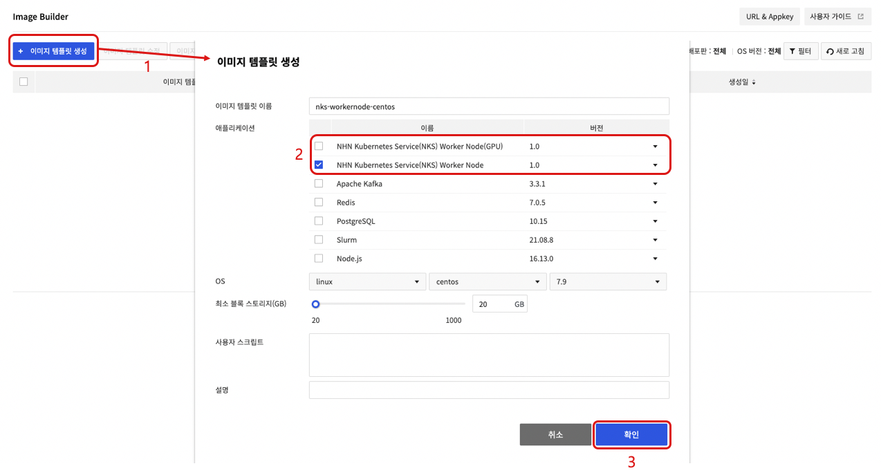
To use a custom image as a worker node image, perform the following process in the Image Builder service.
- Click Create Image Template.
- After selecting the application, write the image template name , OS , minimum block storage (GB), user script, and description.
- For a group of worker nodes that do not use GPU Flavor, choose the NHN Kubernetes Service (NKS) Worker Node application.
- For a group of worker nodes using GPU Flavor, select NHN Kubernetes Service (NKS) Worker Node (GPU) Application.
- Click Confirm to create a image template.
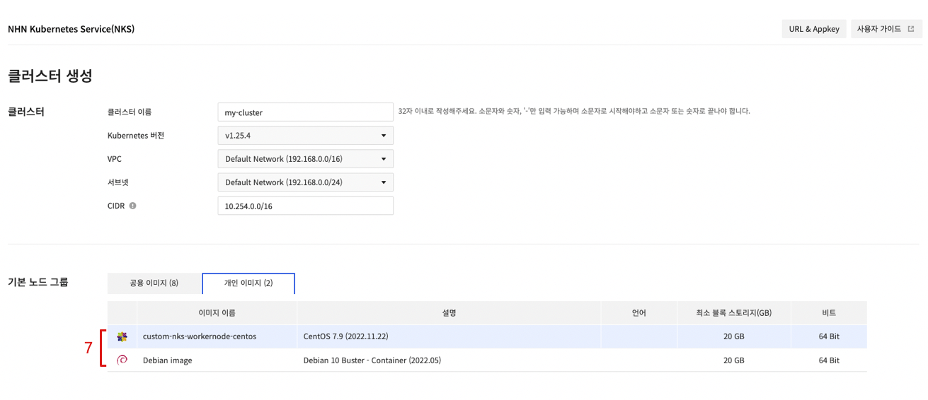
- Select the created image template and choose Build Image.
- On the Build Image screen, select the Private Image tab and select a custom image to convert to a worker node.
- Click Confirm to create a new image after conversion to NKS worker node completes.
- Select the created custom image on the Create Cluster or Create Node Group.

Cluster Management
To run and manage clusters from a remote host, kubectl is required, which is the command-line tool (CLI) provided by Kubernetes.
Installing kubectl
You can use kubectl by downloading an executable file without any special installation process. The download path for each operating system is as follows.
[Caution] If you install Kubernetes-related components such as kubeadm, kubelet, and kubectl using the package manager on worker nodes, the cluster may malfunction. If you are installing kubectl on a worker node, please refer to the download command below to download the file.
| OS | Download Command |
|---|---|
| Linux | curl -LO https://storage.googleapis.com/kubernetes-release/release/v1.15.7/bin/linux/amd64/kubectl |
| MacOS | curl -LO https://storage.googleapis.com/kubernetes-release/release/v1.15.7/bin/darwin/amd64/kubectl |
| Windows | curl -LO https://storage.googleapis.com/kubernetes-release/release/v1.15.7/bin/windows/amd64/kubectl.exe |
For more details on installation and options, see Install and Set Up kubectl.
Change Permission
The downloaded file does not have the execute permission by default. You need to add the execute permission.
$ chmod +x kubectl
Change the Location or Set the Path
Move the file to the path set in the environment variable so that kubectl can be executed on any path, or add the path including kubectl to the environment variable.
- Change the location to a path set in the environment variable
$ sudo mv kubectl /usr/local/bin/
- Add the path to the environment variable
// Executed on the path including kubectl
$ export PATH=$PATH:$(pwd)
Configuration
To access Kubernetes cluster with kubectl, cluster configuration file (kubeconfig) is required. On the NHN Cloud web console, open the Container > NHN Kubernetes Service (NKS) page and select a cluster to access. From Basic Information, click Download of Configuration Files to download a configuration file. Move the downloaded configuration file to a location of your choice to serve it as a reference for kubectl execution.
[Caution] A configuration file downloaded from the NHN Cloud web console includes cluster information and token for authentication. With the file, you're authorized to access corresponding Kubernetes clusters. Take cautions for not losing configuration files.
kubectl requires a cluster configuration file every time it is executed, so a cluster configuration file must be specified by using the --kubeconfig option. However, if the environment variable includes specific path for a cluster configuration file, there is no need to specify each option.
$ export KUBECONFIG={Path of cluster configuration file}
You may copy cluster configuration file path to $HOME/.kube/config, which is the default configuration file of kubectl, if you don't want to save it to an environment variable. However, when there are many clusters, it is easier to change environment variables.
Confirming Connection
See if it is well set by the kubectl version command. If there's no problem, Server Version is printed.
$ kubectl version
Client Version: version.Info{Major:"1", Minor:"15", GitVersion:"v1.15.7", GitCommit:"6c143d35bb11d74970e7bc0b6c45b6bfdffc0bd4", GitTreeState:"clean", BuildDate:"2019-12-11T12:42:56Z", GoVersion:"go1.12.12", Compiler:"gc", Platform:"darwin/amd64"}
Server Version: version.Info{Major:"1", Minor:"15", GitVersion:"v1.15.7", GitCommit:"6c143d35bb11d74970e7bc0b6c45b6bfdffc0bd4", GitTreeState:"clean", BuildDate:"2019-12-11T12:34:17Z", GoVersion:"go1.12.12", Compiler:"gc", Platform:"linux/amd64"}
- Client Version: Version information of executed kubectl file
- Server Version: Kubernetes version information comprising a cluster
CSR (CertificateSigningRequest)
Using Certificate API of Kubernetes, you can request and issue the X.509 certificate for a Kubernetes API client . CSR resource lets you request certificate and decide to accept/reject the request. For more information, see the Certificate Signing Requests document.
CSR Request and Issue Approval Example
First of all, create a private key. For more information on certificate creation, see the Certificates document.
$ openssl genrsa -out dev-user1.key 2048
Generating RSA private key, 2048 bit long modulus
...........................................................................+++++
..................+++++
e is 65537 (0x010001)

$ openssl req -new -key dev-user1.key -subj "/CN=dev-user1" -out dev-user1.csr
Create a CSR resource that includes created private key information and request certificate issuance.
$ BASE64_CSR=$(cat dev-user1.csr | base64 | tr -d '\n')
$ cat <<EOF > csr.yaml -
apiVersion: certificates.k8s.io/v1
kind: CertificateSigningRequest
metadata:
  name: dev-user1
spec:
  groups:
  - system:authenticated
  request: ${BASE64_CSR}
signerName: kubernetes.io/kube-apiserver-client
expirationSeconds: 86400  # one day
  usages:
  - client auth
EOF

$ kubectl apply -f csr.yaml
certificatesigningrequest.certificates.k8s.io/dev-user1 created
The registered CSR is in Pending state. This state indicates waiting for issuance approval or rejection.
$ kubectl get csr
NAME        AGE   SIGNERNAME                            REQUESTOR   REQUESTEDDURATION   CONDITION
dev-user1   3s    kubernetes.io/kube-apiserver-client   admin       24h                 Pending
Approve this certificate issuance request.
$ kubectl certificate approve dev-user1
certificatesigningrequest.certificates.k8s.io/dev-user1 approved
If you check the CSR again, you can see that it has been changed to the Approved,Issued state.
$ kubectl get csr
NAME        AGE   SIGNERNAME                            REQUESTOR   REQUESTEDDURATION   CONDITION
dev-user1   28s   kubernetes.io/kube-apiserver-client   admin       24h                 Approved,Issued
You can look up the certificate as below. The certificate is a value for the Certificate field under Status.
$ apiVersion: certificates.k8s.io/v1
kind: CertificateSigningRequest
metadata:
  annotations:
    kubectl.kubernetes.io/last-applied-configuration: |
      {"apiVersion":"certificates.k8s.io/v1","kind":"CertificateSigningRequest","metadata":{"annotations":{},"name":"dev-user1"},"spec":{"expirationSeconds":86400,"groups":["system:authenticated"],"request":"LS0t..(omitted)","signerName":"kubernetes.io/kube-apiserver-client","usages":["client auth"]}}
  creationTimestamp: "2023-09-15T05:53:12Z"
  name: dev-user1
  resourceVersion: "176619"
  uid: a5813153-40de-4725-9237-3bf684fd1db9
spec:
  expirationSeconds: 86400
  groups:
  - system:masters
  - system:authenticated
  request: LS0t..(omitted)
  signerName: kubernetes.io/kube-apiserver-client
  usages:
  - client auth
  username: admin
status:
  certificate: LS0t..(omitted)
  conditions:
  - lastTransitionTime: "2023-09-15T05:53:26Z"
    lastUpdateTime: "2023-09-15T05:53:26Z"
    message: This CSR was approved by kubectl certificate approve.
    reason: KubectlApprove
    status: "True"
    type: Approved
[Caution] This feature is provided only when the time of cluster creation falls within the following period:
- Pangyo region: Cluster created on December 29, 2020 or later
- Pyeongchon region: Cluster created on December 24, 2020 or later
Admission Controller plugin
The admission controller can intercept a Kubernetes API server request and change objects or deny the request. See Admission Controller for more information about the admission controller. For usage examples of the admission controller, see Admission Controller Guide.
The type of plugin applied to the admission controller varies depending on the cluster version and the time of cluster creation. For more information, see the list of plugins available depending on the time of cluster creation by region.
v1.19.13 or earlier
The following applies to clusters created on February 22, 2021 or earlier for the Pangyo region and clusters created on February 17, 2021 or earlier for the Pyeongchon region.
- DefaultStorageClass
- DefaultTolerationSeconds
- LimitRanger
- MutatingAdmissionWebhook
- NamespaceLifecycle
- NodeRestriction
- ResourceQuota
- ServiceAccount
- ValidatingAdmissionWebhook
The following applies to clusters created on February 23, 2021 or later for the Pangyo region and clusters created on February 18, 2021 or later for the Pyeongchon region.
- DefaultStorageClass
- DefaultTolerationSeconds
- LimitRanger
- MutatingAdmissionWebhook
- NamespaceLifecycle
- NodeRestriction
- PodSecurityPolicy (newly added)
- ResourceQuota
- ServiceAccount
- ValidatingAdmissionWebhook
v1.20.12 or later
All default active admission controllers per Kubernetes version are enabled. The following controllers are activated in addition to the default active admission controllers.
- NodeRestriction
- PodSecurityPolicy
Cluster upgrade
NHN Kubernetes Service (NKS) supports the Kubernetes component upgrade for the currently operating Kubernetes clusters.
Policy of supporting different Kubernetes versions
Kubernetes version is represented as x.y.z. x is the major, y is the minor, and z is the patch version. If features are added, it is a major or minor version upgrade. If it provides features compatible with previous versions such as bug fixes, it is a patch version. For more information about this, see Semantic Versioning 2.0.0.
Kubernetes clusters can upgrade the Kubernetes components while in operation. To this end, each Kubernetes component defines whether to support the features based on the Kubernetes version difference. In minor version, for example, the difference of one version supports the Kubernetes component upgrade for the operating clusters by supporting the mutual feature compatibility. It also defines the upgrade sequence for each type of the components. For more information, see Version Skew Policy.
Feature Behavior
Explains how the Kubernetes cluster upgrade feature supported by NHN Cloud works.
Kubernetes Version Control
NHN Cloud's Kubernetes cluster controls the Kubernetes versions per cluster master and worker node group. Master's Kubernetes version can be checked in the cluster view screen, and the Kubernetes version of the worker node group can be checked in the screen view of each worker node group.
Upgrade Rules
When upgrading, NHN Cloud's Kubernetes Cluster version control and Kubernetes versioning support policy must be followed to keep the proper sequence. The following rules are applied to NHN Cloud's Kubernetes cluster upgrade features.
- Upgrade commands must be given to each master and worker node group.
- In order to upgrade, the Kubernetes version of the master and all worker node groups must match.
- Master must be upgraded first in order to upgrade the worker node group.
- Can be upgraded to the next version of the current version (minor version+1).
- Downgrade is not supported.
- If the cluster is being updated due to the operation of other features, upgrade cannot be proceeded.
The following table shows whether upgrade is possible while upgrading the Kubernetes version. The following conditions are used for the example:
- List of Kubernetes versions supported by NHN Cloud: v1.21.6, v1.22.3, v1.23.3
- Clusters are created as v1.21.6
| Status | Master version | Whether master can be upgraded | Worker node group version | Whether worker node group can be upgraded |
|---|---|---|---|---|
| Initial state | v1.21.6 | Available 1 | v1.21.6 | Unavailable 2 |
| State after master upgrade | v1.22.3 | Unavailable 3 | v1.21.6 | Available 4 |
| State after worker node group upgrade | v1.22.3 | Available 1 | v1.22.3 | Unavailable 2 |
| State after master upgrade | v1.23.3 | Unavailable 3 | v1.22.3 | Available 4 |
| State after worker node group upgrade | v1.23.3 | Unavailable 5 | v1.23.3 | Unavailable 2 |
Notes
- 1: Upgrade is possible because the versions of the master and all worker node groups are matching
- 2: Worker node groups can be upgraded once the master is upgraded
- 3: The versions of the master and all worker node groups must match in order to upgrade
- 4: Upgrade is possible because the master is upgraded
- 5: Upgrade is not possible because the latest version supported by NHN Cloud is being used
Upgrading master components
NHN Cloud's Kubernetes cluster master consists of a number of masters to ensure high availability. Since upgrade is carried out by taking the rolling update method for the master, the availability of the clusters is guaranteed.
The following can happen in this process.
- Kubernetes API can fail temporarily.
Upgrading worker components
Worker components can be upgraded for each worker node group. Worker components are upgraded in the following steps:
- Deactivate the cluster auto scaler feature.1
- Add a buffer node.2 to the worker node group.3
- Perform the following tasks for all worker nodes within the worker node group.4
- Evict working pods from the worker node, and make the node not schedulable.
- Upgrade worker components.
- Make the node schedulable.
- Evict working pods from the buffer node, and delete the buffer node.
- Reactivate the cluster auto scaler feature.1
Notes
- 1: This step is valid only if the cluster autoscaler feature is enabled before starting the upgrade feature.
- 3: Buffer node is an extra node which is created so that the pods evicted from existing worker nodes can be rescheduled during the upgrade process. It is created having the same scale as the worker node defined in that worker node group, and is automatically deleted when the upgrade process is over. This node is charged based on the instance fee policy.
- 3: You can define the number of buffer nodes during upgrade. The default value is 1, and buffer nodes are not added when set to 0. Minimum value of 0, maximum value of (maximum number of nodes per node group - the current number of nodes for the worker node group).
- 4: Tasks are executed by the maximum number of unavailable nodes set during upgrade. The default value of 1, minimum value of 1, and maximum value of the current number of nodes for the worker node group.
The following can happen in this process.
- Pods in service will be evicted and scheduled to another node. (To find out more about pod eviction, refer to the notes below.)
- Auto scale feature does not operate.
[Pod eviction cautions] 1. Pods operated by daemonset controller are not evicted. Daemonset controller runs the pod for each worker node, so the pods run by Daemonset controller cannot run in other nodes. While upgrading the worker node group, the pods run by the Daemonset controller will not be evicted. 2. Pods that use the local storage will lose the previous data as they are evicted. Pods that use the local storage of the node by using
emptyDirwill lose the previous data when being evicted. This is because the storage space in the local node cannot be relocated to another node. 3. Pods that cannot be copied to another node will not be relocated to another node. If the pods run by controllers such as (ReplicationController), (ReplicaSet), (Job), (Daemonset), and (StatefulSet) are evicted, they will be rescheduled to another node by the controller. However, the pods not run by these controllers will not be scheduled to another node after being evicted. 4. Eviction can fail or slow down due to the PodDisruptionBudgets (PDB) setting. You can define the number of pods to maintain with the PodDisruptionBudgets(PDB) setting. Depending on how this setting is set, it may not be possible to evict pods or evicting pods can take longer than normal during upgrade. If pod eviction fails, upgrade fails as well. So if the PDB is enabled, appropriate PDB setting will ensure proper pod eviction. To find out more about PDB setting, see here.
To find out more about safely evicting pods, see Safely Drain a Node.
System Pod Upgrade
If the versions match after upgrading the versions of the master and all worker node groups, the system pod which runs for Kubernetes cluster configuration will be upgraded.
[Caution] If you do not upgrade the worker node group after upgrading the master, some pods might not work properly.
Change Cluster CNI
NHN Kubernetes Service (NKS) supports changing the container network interface (CNI) of a running Kubernetes cluster. The Change Cluster CNI feature allows you to change the CNI of the NHN Kubernetes Service (NKS) from Flannel CNI to Calico CNI.
CNI Change Rules
The following rules apply to the Kubernetes Cluster CNI change feature in the NHN Cloud.
- The CNI change feature is available for the NHN Kubernetes Service (NKS) v1.24.3 and above.
- The CNI change is only available if the CNI being used by the existing NHN Kubernetes Service (NKS) is Flannel.
- At the start of the CNI change, the task is collectively done on the master and all worker node groups.
- The CNI change is possible only when the Kubernetes version of the master matches the Kubernetes version of all worker node groups.
- CNI change from Calico to Flannel is not supported.
- CNI change is not possible when the cluster is being updated due to other features being operated.
The following example shows a table of possible changes during the Kubernetes CNI change process. The conditions used in the example are as follows.
List of Kubernetes versions supported by NHN Cloud: v1.23.3, v1.24.3, v1.25.4 Clusters are created as v1.23.3
| Status | Cluster Version | Current CNI | CNI Change Available |
|---|---|---|---|
| Initial state | v1.23.3 | Flannel | Unavailable1 |
| Status after cluster upgrade | v1.24.3 | Flannel | Available2 |
| Status after CNI change | v1.24.3 | Calico | Unavailable3 |
Notes
- 1: CNI change is unavailable because the cluster version is below 1.24.3
- 2: CNI change is available because the cluster version is 1.24.3 or higher.
- 3: CNI change is unavailable because CNI is already Calico
Change Process from Flannel to Calico CNI
CNI change proceeds in the following order.
- Add buffer nodes 1 to all worker node groups.2
- Calico CNI is deployed on the cluster.3
- Disable the cluster Auto scale feature.4
- Perform the following jobs sequentially for all worker nodes in all worker node groups. 5
- Evict working pods from the worker node, and make the node not schedulable.
- Reassign the worker node's pod IPs to Calico CIDR. Any pod deployed on the node is to be redeployed. 6
- Make the node schedulable.
- Evict working pods from the buffer node, and delete the buffer node.
- Re-enables cluster Auto scale feature 4.
- Delete Flannel CNI.
Notes
- 1: A buffer node is a free node that is created so that the pod evicted from the existing worker node can be rescheduled during the CNI change process. It is created as a node of the same specification as the worker node defined in the corresponding worker node group and is automatically deleted at the end of the upgrade process. This node is charged in accordance with the Instance pricing policy.
- 2: You can set the number of buffer nodes when changing CNI. Defaults to 1. If set to 0, no buffer nodes are added. The minimum is 0 and the maximum is (maximum number of nodes per node group - the current number of nodes in that worker node group).
- 3: When Calico CNI is deployed in a cluster, the Flannel and Calico CNI coexist. In this state, when a new pod is deployed, the pod IP is set to Flannel CNI and then deployed. A pod with Flannel CIDR IP and a pod with Calico CIDR IP can communicate with each other.
- 4: This step is valid only if the cluster Auto scale feature is enabled before starting upgrade features.
- 5: Perform jobs as many as the maximum number of unavailable nodes set when changing the CNI. Default value is 1. Minimum value is 1, and maximum value is the number of all nodes in the current cluster.
- 6: The IPs of the existing deployed Pods are all assigned with Flannel CIDRs. To change to Calico CNI, redeploy all the pods that have IP assigned to the Flannel CIDR to reassign Calico CIDR IP. When a new pod is deployed, the pod IP is set to Calico CNI and deployed.
The following can happen in this process.
- The pod in service is evicted and scheduled to another node. (For more information on pod eviction, ss Cluster Upgrade).
- All the pods deployed in the cluster are redeployed. (For more information on redeploying pods, see the precautions for pod redeployment below.)
- Auto scale feature does not operate.
[Precautions for pod redeployment] 1. It proceeds for the pod that has not been transferred to another node through the evicting process. 2. For normal communication between Flannel CIDR and Calico CIDR during the CNI change process, CNI change pod network value should not be the same as the existing Flannel CIDR value. 3. Pause containers of the previously distributed pod are all stopped and then regenerated by kubelet. The settings, such as the pod name and local storage space, remain unchanged, but the IP is changed to the IP of Calico CIDR.
Enforce IP Access Control to Cluster API Endpoints
You can enforce or disable IP access control to cluster API endpoints. For more information about the IP access control feature, see IP Access Control.
IP Access Control Rules
When you add a Cluster API endpoint to IP access control targets, the rules below apply.
- If the IP access control type is set to Allow, the cluster default subnet CIDR is automatically added to the access control target.
- If the IP access control type is set to Allow, the Dashboard, Namespaces, Workloads, Services & Network, Storage, Settings, and Events tabs in the NKS console are disabled.
- If the IP access control type is set to Block, requests are denied if an IP band that overlaps the cluster default subnet CIDR band is in the access control target list.
- The maximum number of IP access control targets you can set is 100.
- At least one IP access control target must exist.
Manage Worker Node
Manage Container
Clusters of Kubernetes v1.24.3 or older
Clusters of Kubernetes v1.24.3 or older use Docker to comprise the container runtime. In the worker node, you can use the docker CLI to view the container status and the container image. For more details and usage on the docker CLI, see Use the Docker command line.
Clusters of Kubernetes v1.24.3 and later
Clusters of Kubernetes v1.24.3 or later use containerd to comprise the container runtime. In the worker node, you can use nerdctl instead of the docker CLI to view the container status and the container image. For more details and usage on nerdctl, see nerdctl: Docker-compatible CLI for containerd.
Manage Network
Default Network Interface
Every worker node has a network interface that connects to the VPC/subnet entered when creating the cluster. This default network interface is named "eth0", and worker nodes connect to the master through this network interface.
Additional Network Interface
If you set additional networks when creating a cluster or worker node group, additional network interfaces are created on the worker nodes of that worker node group. Additional network interfaces are named eth1, eth2, ... in the order entered in the additional network settings.
Default Route Settings
If multiple network interfaces exist on a worker node, a default route is set for each network interface. If multiple default routes are set on a system, the default route with the lowest metric value acts as the system default route. Default routes per network interface have lower metric values for smaller interface numbers. This causes the smallest numbered network interface among active network interfaces to act as the system default route.
To set the system default route as an additional network interface, the following tasks are required.
1. Change Metric Settings per Network Interface
All network interfaces of a worker node are assigned an IP address through a DHCP server. Set the default route for each network interface when an IP address is assigned from a DHCP server. At this time, the metric value of each default route is preset for each interface. The storage location and setting items for each Linux distribution are as follows.
- CentOS
- Configuration file location: /etc/sysconfig/network-scripts/ifcfg-{network interface name}
- Configuration item for metric value: METRIC
- Ubuntu
- Configuration file location: /etc/systemd/network/toastcloud-{network interface name}.network
- Configuration item for metric value: RouteMetric in DHCP section
[Note] The metric value for each default route is determined when the default route is set. Therefore, the changed settings will take effect at the time of setting the next default route. To change the metric value for each route currently applied to the system, refer to
Change Metric Value for the Current Routebelow.
2. Change Metric Value for the Current Route
To change the system default route, you can adjust the metric value of the default route for each network interface. The following is an example of adjusting the metric value of each default route using the route command.
Below is the state before running the task. You can find that the smaller interface number has the lower metric value.
# route -n
Kernel IP routing table
Destination     Gateway         Genmask         Flags Metric Ref    Use Iface
0.0.0.0         10.0.0.1        0.0.0.0         UG    0      0        0 eth0
0.0.0.0         192.168.0.1     0.0.0.0         UG    100    0        0 eth1
0.0.0.0         172.16.0.1      0.0.0.0         UG    200    0        0 eth2
...
To set eth1 as the system default route, change the metric value for eth1 to 0 and the metric value for eth0 to 100. Since you can't just change the metric value, you must delete the route and add it again. First, delete the route of eth0 and set the metric value for eth0 to 100.
# route del -net 0.0.0.0/0 dev eth0
# route add -net 0.0.0.0/0 gw 10.0.0.1 dev eth0 metric 100
Also delete the route of eth1 first, and set the metric value for eth1 to 0.
# route del -net 0.0.0.0/0 dev eth1
# route add -net 0.0.0.0/0 gw 192.168.0.1 dev eth1 metric 0
When you look up the route, you can find that the metric value has changed.
# route -n
Kernel IP routing table
Destination     Gateway         Genmask         Flags Metric Ref    Use Iface
0.0.0.0         192.168.0.1     0.0.0.0         UG    0      0        0 eth1
0.0.0.0         10.0.0.1        0.0.0.0         UG    100    0        0 eth0
0.0.0.0         172.16.0.1      0.0.0.0         UG    200    0        0 eth2
...
Change Default Route Settings using User Script
If you use the User Script feature, the above settings can be maintained even when a node is newly initialized due to node scale-out. The following user script is an example of setting the metric value of eth0 to 100 and the metric value of eth1 to 0 on a worker node using CentOS. This also changes the metric value for default route currently applied to the system, which persist after the worker node restarts.
#!/bin/bash
sed -i -e 's|^METRIC=.*$|METRIC=100|g' /etc/sysconfig/network-scripts/ifcfg-eth0
sed -i -e 's|^METRIC=.*$|METRIC=0|g' /etc/sysconfig/network-scripts/ifcfg-eth1
route del -net 0.0.0.0/0 dev eth0
route add -net 0.0.0.0/0 gw 10.0.0.1 dev eth0 metric 100
route del -net 0.0.0.0/0 dev eth1
route add -net 0.0.0.0/0 gw 192.168.0.1 dev eth1 metric 0
Set kubelet Custom Arguments
A kubelet is a node agent that runs on all worker nodes. The kubelet receives input for many settings using command-line arguments. The kubelet custom arguments setting feature provided by NKS allows you to add arguments that are input at kubelet startup. You can set up kubelet custom arguments and apply them to your system as follows.
- Enter your custom arguments in the
/etc/kubernetes/kubelet-user-argsfile on the worker node in the formKUBELET_USER_ARGS="custom arguments". - Run the
systemctl daemon-reloadcommand. - Run the
systemctl restart kubeletcommand. - Determine whether the kubelet is working properly with the
systemctl status kubeletcommand.
[Caution] * This feature will only work for clusters newly created after November 28, 2023. * This feature runs on each worker node for which you want to set custom arguments. * The kubelet will not behave correctly when you enter an incorrectly formatted custom argument. * The set custom argument will remain in effect even when the system restarts.
Custom Containerd Registry Settings
NKS clusters in v1.24.3 and later use containerd v1.6 as the container runtime. NKS provides the feature to customize several settings in containerd, including those related to the registry, to suit your environment. For registry settings in containerd v1.6, see Configure Image Registry.
While initializing worker nodes, if a custom containerd registry configuration file(``/etc/containerd/registry-config``.json) exists, the contents of this file are applied to the containerd configuration file(/etc/containerd/config.toml). If a custom containerd registry configuration file does not exist, the containerd configuration file applies the default registry settings. The default registry settings include the following
[
   {
      "registry": "docker.io",
      "endpoint_list": [
         "https://registry-1.docker.io"
      ]
   }
]
The following key/value formats can be set for one registry
{
  "registry": "REGISTRY_NAME",
  "endpoint_list": [
     "ENDPOINT1",
     "ENDPOINT2"
  ],
  "tls": {
     "ca_file": "CA_FILEPATH",
     "cert_file": "CERT_FILEPATH",
     "key_file": "KEY_FILEPATH",
     "insecure_skip_verify": true_or_false
  },
  "auth": {
     "username": "USERNAME",
     "password": "PASSWORD",
     "auth": "AUTH",
     "identitytoken": "IDENTITYTOKEN"
  }
}
Example 1
If you want to register additional registries in addition to docker.io, you can set up as follows.
[
   {
      "registry": "docker.io",
      "endpoint_list": [
         "https://registry-1.docker.io"
      ]
   },
   {
      "registry": "additional.registry.io",
      "endpoint_list": [
         "https://additional.registry.io"
      ]
   }
]
Example 2
If you want to remove the docker.io registry and only register registries that support HTTP, you can set up as follows.
[
   {
      "registry": "user-defined.registry.io",
      "endpoint_list": [
         "http://user-defined.registry.io"
      ],
      "tls": {
         "insecure_skip_verify": true
      }
   }
]
Example 3
To generate a custom containerd registry configuration file with the contents of Example 2 upon node creation, you can set up a user script as follows
mkdir -p /etc/containerd
echo '[ { "registry": "user-defined.registry.io", "endpoint_list": [ "http://user-defined.registry.io" ], "tls": { "insecure_skip_verify": true } } ]' > /etc/containerd/registry-config.json
[Caution] * The containerd configuration file
(/etc/containerd/config.toml) is a file that is managed by NKS. Arbitrary modifications to this file can cause errors in the behavior of NKS features or remove the modifications. * If an incorrect registry is set with the custom containerd registry setup feature, worker nodes can work abnormally. * The point at which the custom containerd registry settings feature is applied to the containerd configuration file is during worker node initialization. The worker node initialization process is part of the worker node creation process and the worker node group upgrade process. * To apply the custom container registry settings feature when creating a worker node, you must have your user script generate this configuration file. * To apply the custom container registry settings feature when upgrading a group of worker nodes, you must manually set this file on all worker nodes before proceeding with the upgrade. * If a custom containerd registry settings file exists, the settings in this file will be applied to containerd. * To use thedocker.ioregistry, you must also include settings for thedocker.ioregistry. For settings for thedocker.ioregistry, see Default registry settings. * If you do not want to use thedocker.ioregistry, you can simply not include any settings for thedocker.ioregistry. However, at least one registry setting must exist.
LoadBalancer Service
Pod is a basic execution unit of a Kubernetes application and it is connected to a cluster network via CNI (container network interface). By default, pods are not accessible from outside the cluster. To expose a pod's services to the outside of the cluster, you need to create a path to expose to the outside using the Kubernetes LoadBalancer Service object. Creating a LoadBalancer service object creates an NHN Cloud Load Balancer outside the cluster and associates it with the service object.
Creating Web Server Pods
Write a deployment object manifest file that executes two nginx pods as follows and create an object.
# nginx.yaml
apiVersion: apps/v1
kind: Deployment
metadata:
  name: nginx-deployment
  labels:
    app: nginx
spec:
  replicas: 2
  selector:
    matchLabels:
      app: nginx
  template:
    metadata:
      labels:
        app: nginx
    spec:
      containers:
      - name: nginx
        image: nginx:1.14.2
        ports:
        - containerPort: 80
With deployment object created, pods defined at manifest are automatically created.
$ kubectl apply -f nginx.yaml
deployment.apps/nginx-deployment created

$ kubectl get pods
NAME                                READY   STATUS    RESTARTS   AGE
nginx-deployment-7fd6966748-pvrzs   1/1     Running   0          4m13s
nginx-deployment-7fd6966748-wv7rd   1/1     Running   0          4m13s
Creating LoadBalancer
To define service object of Kubernetes, a manifest comprised of the following items is required:
| Item | Description |
|---|---|
| metadata.name | Name of service object |
| spec.selector | Name of pod to be associated with service object |
| spec.ports | Interface setting to deliver incoming traffic from external load balancer to a pod |
| spec.ports.name | Name of interface |
| spec.ports.protocol | Protocol for an interface (e.g: TCP) |
| spec.ports.port | Port number to be made public out of service object |
| spec.ports.targetPort | Port number of a pod to be associated with service object |
| spec.type | Type of service object |
Service manifest is written like below. The LoadBalancer service object is associated with a pod labelled as app: nginx, following the defined name at spec.selector. And as spec.ports defines, traffic inflow via TCP/8080 is delivered to the TCP/80 port of the pod.
# service.yaml
apiVersion: v1
kind: Service
metadata:
  name: nginx-svc
  labels:
    app: nginx
spec:
  ports:
  - port: 8080
    targetPort: 80
    protocol: TCP
  selector:
    app: nginx
  type: LoadBalancer
When the LoadBalancer service object is created, it takes some time to create and associate a load balancer externally. Before associated with external load balancer, EXTERNAL-IP shows <pending>.
$ kubectl apply -f service.yaml
service/nginx-svc created

$ kubectl get service
NAME         TYPE           CLUSTER-IP      EXTERNAL-IP   PORT(S)          AGE
nginx-svc    LoadBalancer   10.254.134.18   <pending>     8080:30013/TCP   11s
When it is associated with external load balancer, EXTERNAL-IP shows IP, which refers to floating IP of external load balancer.
$ kubectl get service
NAME         TYPE           CLUSTER-IP      EXTERNAL-IP      PORT(S)          AGE
nginx-svc    LoadBalancer   10.254.134.18   123.123.123.30   8080:30013/TCP   3m13s
[Note] You can view the created load balancer on the Network > Load Balancer page. Load balancer IP is a floating IP allowing external access. You can check it on the Network > Floating IP page.
Testing Service on Internet
Send an HTTP request via floating IP associated with load balancer to see if the web server pod of a Kubernetes cluster responds. Since the TcP/8080 port of a service object is attached to TCP/80 port of a pod, request must be sent to the TCP/8080 port. If external load balancer, service object, and pod are well associated, the web server shall respond to nginx default page.
$ curl http://123.123.123.30:8080
<!DOCTYPE html>
<html>
<head>
<title>Welcome to nginx!</title>
<style>
    body {
        width: 35em;
        margin: 0 auto;
        font-family: Tahoma, Verdana, Arial, sans-serif;
    }
</style>
</head>
<body>
<h1>Welcome to nginx!</h1>
<p>If you see this page, the nginx web server is successfully installed and
working. Further configuration is required.</p>

<p>For online documentation and support please refer to
<a href="http://nginx.org/">nginx.org</a>.<br/>
Commercial support is available at
<a href="http://nginx.com/">nginx.com</a>.</p>

<p><em>Thank you for using nginx.</em></p>
</body>
</html>
Setting Detailed Options for Load Balancer
When defining service objects in Kubernetes, you can set several options for the load balancer. You can set the following.
- Global Setting and Per-Listener Setting
- Format of Per-Listener Setting
- Setting Load Balancer Name
- Setting keep-alive timeout
- Set load balancer type
- Set the session affinity
- Set whether to keep a floating IP address when deleting the load balancer
- Set the load balancer IP
- Set whether to use the floating IP
- Set VPC
- Set Subnet
- Set Member Subnet
- Set the listener connection limit
- Set the listener protocol
- Set the listener proxy protocol
- Set the load balancing method
- Set the health check protocol
- Set the health check interval
- Set the health check maximum response time
- Set the maximum number of retries for a health check
Global Setting and Per-Listener Setting
For each setting item, global setting or per-listener setting is supported. If neither global nor per-listener setting is available, the default value for each setting is used. * Per-listener setting: A setting that applies only to the target listener. * Global setting: If the target listener doesn't have a per-listener setting, this setting is applied.
Format of Per-Listener Setting
Per-listener settings can be set by appending a prefix representing the listener to the global settings key. The prefix representing the listener is the service object's port protocol (spec.ports[].protocol) and port number (spec.ports[].port) concatenated with a dash (-). For example, if the protocol is TCP and the port number is 80, the prefix is TCP-80. If you want to set session affinity for the listener associated with this port, you can set it in TCP-80.loadbalancer.nhncloud/pool-session-persistence under .metadata.annotations.
The manifest below is an example of mixing the global setting and per-listener settings.
apiVersion: v1
kind: Service
metadata:
  name: echosvr-svc
  labels:
    app: echosvr
  annotations:
    # Global setting
    loadbalancer.nhncloud/pool-lb-method: SOURCE_IP

    # Per-listener settings
    TCP-80.loadbalancer.nhncloud/pool-session-persistence: "SOURCE_IP"
    TCP-80.loadbalancer.nhncloud/listener-protocol: "HTTP"
    TCP-443.loadbalancer.nhncloud/pool-lb-method: LEAST_CONNECTIONS
    TCP-443.loadbalancer.nhncloud/listener-protocol: "TCP"
spec:
  ports:
  - name: tcp-80
    port: 80
    targetPort: 8080
    protocol: TCP
  - name: tcp-443
    port: 443
    targetPort: 8443
    protocol: TCP
  selector:
    app: echosvr
  type: LoadBalancer
When this manifest is applied, the per-listener settings are set as shown in the following table.
| Item | TCP-80 listener | TCP-433 listener | Description |
|---|---|---|---|
| Load Balancing Method | SOURCE_IP | LEAST_CONNECTIONS | TCP-80 listener is set to SOURCE_IP according to the global setting TCP-443 listener is set to LEAST_CONNECTIONS according to the per-listener setting |
| Session Affinity | SOURCE_IP | None | TCP-80 listener is set to SOURCE_IP according to the per-listener setting TCP-443 listener is set to None by the default value |
| Listener Protocol | HTTP | TCP | Both the TCP-80 listener and the TCP-443 listener are set according to the per-listener settings |
[Note] The features without additional version information are only applicable to clusters of Kubernetes v1.19.13 or later. For clusters of Kubernetes v1.19.13 version, per-listener settings apply only to clusters created on January 25, 2022 or after.
[Caution] All setting values for the features below must be entered in string format. In the YAML file input format, to enter in string format regardless of the input value, enclose the input value in double quotation marks ("). For more information about the YAML file format, see Yaml Cookbook.
Setting Load Balancer Name
You can set a name for the load balancer.
- The setting location is loadbalancer.nhncloud/loadbalancer-name under .metadata.annotations.
- Per-listener settings cannot be applied.
- Only alphanumerics, -, and _ are allowed.
- If it contains invalid characters, the load balancer name is set according to the default load balancer name form.
- Default load balancer name form: "kube_service_{CLUSTER_UUID}{SERVICE_NAMESPACE}{SERVICE_NAME}"
- The maximum length is 255 characters, and the load balancer name is truncated to 255 characters if the maximum length is exceeded.
[Caution] The following cases can cause serious malfunction of the load balancer. * Modifying the load balancer name after the service object is created * Creating a load balancer with a duplicate name within the same project
Set load balancer type
You can set the load balancer type. For more information, see Load Balancer Console User Guide.
- The setting location is loadbalancer.nhncloud/loadbalancer-type under .metadata.annotations.
- Per-listener settings cannot be applied.
- It can be set to one of the following.
- shared: A load balancer in the 'regular' type is created. Default value when not set.
- dedicated: A load balancer in the ‘dedicated’ type is created.
- physical_basic: A load balancer in the 'physical basic' type is created.
- physical_premium: A load balancer in the 'physical premium' type is created.
[Caution] Physical load balancer is only provided in Korea (Pyeongchon) region. You cannot attach physical load balancers to floating IPs. Instead, a public IP that is automatically assigned when creating the physical load balancer is used as an IP to receive traffic targeted for balancing. This public IP is shown as a service IP in the console. For the above characteristics, you cannot see the exact status of the load balancer (including the associated floating IP) through Kubernetes service objects. Please check the status of physical load balancers in the console.
Set the session affinity
You can set the session affinity for the load balancer.
- The setting location is loadbalancer.nhncloud/pool-session-persistence under .metadata.annotations.
- Per-listener settings can be applied.
- It can be set to one of the following.
- Empty string (""): Set session affinity to 'None'. The default when not set.
- SOURCE_IP: Set session affinity to SOURCE_IP.
- If the load balancing method is SOURCE_IP, the session affinity setting is ignored, and the session affinity setting is set to None.
- Clusters of v1.17.6, v1.18.19
- Changes cannot be made after the load balancer is created.
- Clusters of v1.19.13 or later
- The setting can be changed even after the load balancer is created.
Set whether to keep a floating IP address when deleting the load balancer
The load balancer has a floating IP associated with it. You can set whether to delete or keep the floating IP associated with the load balancer when deleting the load balancer.
- The setting location is loadbalancer.openstack.org/keep-floatingip under .metadata.annotations.
- Per-listener settings cannot be applied.
- It can be set to one of the following.
- true: Keep the floating IP.
- false: Delete the floating IP. The default when not set.
[Caution] v1.18.19 clusters created before October 26, 2021 have an issue where floating IPs are not deleted when the load balancer is deleted. If you contact us through 1:1 inquiry of the Customer Center, we will provide detailed information on the procedure to solve this issue.
Set the load balancer IP
You can set the load balancer IP when creating a load balancer.
- The setting location is .spec.loadBalancerIP.
- Per-listener settings cannot be applied.
- It can be set to one of the following.
- Empty string(""): Associate an automatically created floating IP with the load balancer. The default when not set.
: Associate the existing floating IP with the load balancer. It can be used when there is a floating IP that is allocated and not associated.
The following is an example of manifest for associating a custom floating IP to the load balancer.
# service-fip.yaml
apiVersion: v1
kind: Service
metadata:
  name: nginx-svc-floatingIP
  labels:
    app: nginx
spec:
  loadBalancerIP: <Floating_IP>
  ports:
  - port: 8080
    targetPort: 80
    protocol: TCP
  selector:
    app: nginx
  type: LoadBalancer
Set whether to use the floating IP
You can set whether to use floating IPs when creating the load balancer.
- The setting location is service.beta.kubernetes.io/openstack-internal-load-balancer under .metadata.annotaions.
- Per-listener settings cannot be applied.
- It can be set to one of the following.
- true: Use a VIP (Virtual IP), not a floating IP.
- false: Use a floating IP. The default when not set.
- If you are using a VIP, you can specify the VIP to connect to the load balancer instead of the automatically created VIP by setting the .spec.loadBalancerIP entry together.
The following is an example of manifest for associating a custom VIP with the load balancer.
# service-vip.yaml
apiVersion: v1
kind: Service
metadata:
 name: nginx-svc-fixedIP
 labels:
   app: nginx
 annotations:
   service.beta.kubernetes.io/openstack-internal-load-balancer: "true"
spec:
 loadBalancerIP: <Virtual_IP>
 ports:
 - port: 8080
   targetPort: 80
   protocol: TCP
 selector:
   app: nginx
 type: LoadBalancer
Depending on the combination of floating IP usage and load balancer IP setting, it works as follows.
| Set whether to use the floating IP | Set the load balancer IP | Description |
|---|---|---|
| false | not set | Associate a floating IP with the load balancer. |
| false | set | Associate a specified floating IP with the load balancer. |
| true | not set | Automatically set a VIP associated with the load balancer. |
| true | set | Associate a specified VIP with the load balancer. |
Set VPC
You can set a VPC to which the load balancer is connected when creating a load balancer.
- The setting location is loadbalancer.openstack.org/network-id under .metadata.annotaions.
- Per-listener settings cannot be applied.
- If not set, it is set to the VPC configured when creating the cluster.
Set Subnet
You can set a subnet to which the load balancer is connected when creating a load balancer. The load balancer's private IP is connected to the set subnet. If no member subnet is set, worker nodes connected to this subnet are added as load balancer members.
- The setting location is loadbalancer.openstack.org/subnet-id under .metadata.annotaions.
- Per-listener settings cannot be applied.
- If not set, it is set to the subnet configured when creating the cluster.
Below is an manifest example of setting a VPC and subnet for the load balancer.
apiVersion: v1
kind: Service
metadata:
  name: nginx-svc-vpc-subnet
  labels:
     app: nginx
  annotations:
    loadbalancer.openstack.org/network-id: "49a5820b-d941-41e5-bfc3-0fd31f2f6773"
    loadbalancer.openstack.org/subnet-id: "38794fd7-fd2e-4f34-9c89-6dd3fd12f548"
spec:
  ports:
  - port: 8080
    targetPort: 80
    protocol: TCP
  selector:
    app: nginx
  type: LoadBalancer
Set Member Subnet
When creating a load balancer, you can set a subnet to which load balancer members will be connected. Worker nodes connected to this subnet are added as load balancer members.
- The setting is located at loadbalancer.nhncloud/member-subnet-id under .metadata.annotaions.
- Per-listener settings cannot be applied.
- If not set, the load balancer's subnet setting is applied.
- The member subnet must be in the same VPC as the load balancer subnet.
- To set up more than one member subnet, enter them as a comma-separated list.
Below is an manifest example of setting a VPC, subnet, and member subnet for the load balancer.
apiVersion: v1
kind: Service
metadata:
  name: nginx-svc-vpc-subnet
  labels:
     app: nginx
  annotations:
    loadbalancer.openstack.org/network-id: "49a5820b-d941-41e5-bfc3-0fd31f2f6773"
    loadbalancer.openstack.org/subnet-id: "38794fd7-fd2e-4f34-9c89-6dd3fd12f548"
    loadbalancer.nhncloud/member-subnet-id: "c3548a5e-b73c-48ce-9dc4-4d4c484108bf"
spec:
  ports:
  - port: 8080
    targetPort: 80
    protocol: TCP
  selector:
    app: nginx
  type: LoadBalancer
[Caution] Member subnets can be set up on clusters that have been upgraded to v1.24.3 or later after November 28, 2023, or are newly created.
Set the listener connection limit
You can set the connection limit for a listener.
- The setting location is loadbalancer.nhncloud/connection-limit under .metadata.annotations.
- Per-listener settings can be applied.
- Clusters of v1.17.6, v1.18.19
- Minimum value of 1, maximum value of 60000.
- It you do not set it, it is set to -1, and the value applied to the actual load balancer is 2000.
- Clusters of v1.19.13 or later
- Minimum value of 1, maximum value of 60000.
- If not set or a value out of range is entered, it is set to the default value of 60000.
Set the listener protocol
You can set the protocol of the listener.
- The setting location is loadbalancer.nhncloud/listener-protocol under .metadata.annotations.
- Per-listener settings can be applied.
- It can be set to one of the following.
- TCP: The default when not set.
- HTTP
- HTTPS
- TERMINATED_HTTPS: Set it to TERMINATED_HTTPS. SSL version, certificate, and private key information must be set additionally.
[Caution] The listener protocol setting is not applied to the load balancer even if you change the service object. To change the listener protocol setting, you must delete the service object and then create it again. Note that the load balancer is deleted and then re-created in this case.
The SSL version can be set as follows:
- The setting location is loadbalancer.nhncloud/listener-terminated-https-tls-version under .metadata.annotations.
- Per-listener settings can be applied.
- It can be set to one of the following.
- TLSv1.3: The default when not set.
- TLSv1.2
- TLSv1.1
- TLSv1.0_2016
- TLSv1.0
- SSLv3
[Caution] TLSv1.3 can be set in clusters created after March 29, 2022.
Certificate information can be set as follows:
- The setting location is loadbalancer.nhncloud/listener-terminated-https-cert under .metadata.annotations.
- Per-listener settings can be applied.
- It must include start and end lines.
Private key information can be set as follows:
- The setting location is loadbalancer.nhncloud/listener-terminated-https-key under .metadata.annotations.
- Per-listener settings can be applied.
- It must include start and end lines.
The following is an example of manifest for setting the listener protocol to TERMINATED_HTTPS. Certificate information and private key information are partially omitted.
metadata:
  name: echosvr-svc
  labels:
    app: echosvr
  annotations:
    loadbalancer.nhncloud/listener-protocol: TERMINATED_HTTPS
    loadbalancer.nhncloud/listener-terminated-https-tls-version: TLSv1.2
    loadbalancer.nhncloud/listener-terminated-https-cert: |
      -----BEGIN CERTIFICATE-----
      MIIDZTCCAk0CCQDVfXIZ2uxcCTANBgkqhkiG9w0BAQUFADBvMQswCQYDVQQGEwJL
      ...
      fnsAY7JvmAUg
      -----END CERTIFICATE-----
    loadbalancer.nhncloud/listener-terminated-https-key: |
      -----BEGIN RSA PRIVATE KEY-----
      MIIEowIBAAKCAQEAz+U5VNZ8jTPs2Y4NVAdUWLhsNaNjRWQm4tqVPTxIrnY0SF8U
      ...
      u6X+8zlOYDOoS2BuG8d2brfKBLu3As5VAcAPLcJhE//3IVaZHxod
      -----END RSA PRIVATE KEY-----
Set the listener proxy protocol
When the listener protocol is TCP or HTTPS, you set the proxy protocol to the listener. For more information on proxy protocol, see Load Balancer Proxy Mode
- The setting location is loadbalancer.nhncloud/listener-protocol under .metadata.annotations.
- Per-listener settings can be applied.
- It can be set to one of the following.
- true: Enable the proxy protocol.
- false: Disable the proxy protocol. Default when not set.
Set the load balancing method
You can set the load balancing method.
- The setting location is loadbalancer.nhncloud/pool-lb-method under .metadata.annotations.
- Per-listener settings can be applied.
- It can be set to one of the following.
- ROUND_ROBIN: The default when not set.
- LEAST_CONNECTIONS
- SOURCE_IP
Set the health check protocol
You can set the health check protocol.
- The setting location is loadbalancer.nhncloud/healthmonitor-type under .metadata.annotations.
- Per-listener settings can be applied.
- It can be set to one of the following.
- HTTP: You must additionally set HTTP URL, HTTP method, and HTTP status code.
- HTTPS: You must additionally set HTTP URL, HTTP method, and HTTP status code.
- TCP: The default when not set.
The HTTP URL can be set as follows:
- The setting location is loadbalancer.nhncloud/healthmonitor-http-url under .metadata.annotations.
- Per-listener settings can be applied.
- The setting value must start with /.
- If not set or a value that does not match the rule is entered, it is set to the default value of /.
The HTTP method can be set as follows:
- The setting location is loadbalancer.nhncloud/healthmonitor-http-method under .metadata.annotations.
- Per-listener settings can be applied.
- Currently, only GET is supported. If not set or another value is entered, it will be set to GET, which is the default value.
The HTTP status code can be set as follows:
- The setting location is loadbalancer.nhncloud/healthmonitor-http-expected-code under .metadata.annotations.
- Per-listener settings can be applied.
- You can enter the value in the form of a single value (e.g. 200), a list (e.g. 200,202), or a range (e.g. 200-204).
- If not set or a value that does not match the rule is entered, it is set to the default value of 200.
Set the health check interval
You can set the health check interval.
- The setting location is loadbalancer.nhncloud/healthmonitor-delay under .metadata.annotations.
- Per-listener settings can be applied.
- Set the value in seconds.
- Minimum value of 1, maximum value of 5000.
- If not set or a value out of range is entered, it is set to the default value of 60.
Set the health check maximum response time
You can set the maximum response time for health checks.
- The setting location is loadbalancer.nhncloud/healthmonitor-timeout under .metadata.annotations.
- Per-listener settings can be applied.
- Set the value in seconds.
- Minimum value of 1, maximum value of 5000.
- This setting must be smaller than the Health check interval setting setting value.
- If not set or a value out of range is entered, it is set to the default value of 30.
- However, if the input value or setting value is greater than the Health check interval setting, it is set to 1/2 of the Health check interval setting setting value.
Set the maximum number of retries for a health check
You can set the maximum number of retries for a health check.
- The setting location is loadbalancer.nhncloud/healthmonitor-max-retries under .metadata.annotations.
- Per-listener settings can be applied.
- Minimum value of 1, maximum value of 10.
- If not set or a value out of range is entered, it is set to the default value of 3.
Setting keep-alive timeout
You can set a keep-alive timeout value.
- The setting is located at loadbalancer.nhncloud/keepalive-timeout under .metadata.annotations.
- Per-listener settings can be applied.
- Set the value in seconds.
- The minimum value is 0 and the maximum is 3600.
- If not set or a value out of range is entered, it is set to the default value of 300.
[Caution] The keep-alive timeout can be set up on clusters that have been upgraded to v1.24.3 or later after November 28, 2023, or are newly created.
Ingress Controller
Ingress Controller routes HTTP and HTTPS requests from cluster externals to internal services, in reference of the rules that are defined at ingress object so as to provide SSL/TSL closure and virtual hosting. For more details on Ingress Controller and Ingress, see Ingress Controller, Ingress.
Installing NGINX Ingress Controller
NGINX Ingress Controller is one of the most frequently used ingress controllers. For more details, see NGINX Ingress Controller and NGINX Ingress Controller for Kubernetes. For installation of NGINX Ingress Controller, see Installation Guide.
Diverging Service on URI
Ingress controller can diverge services based on URI. The following figure shows the structure of a simple example of service divergence based on URI.
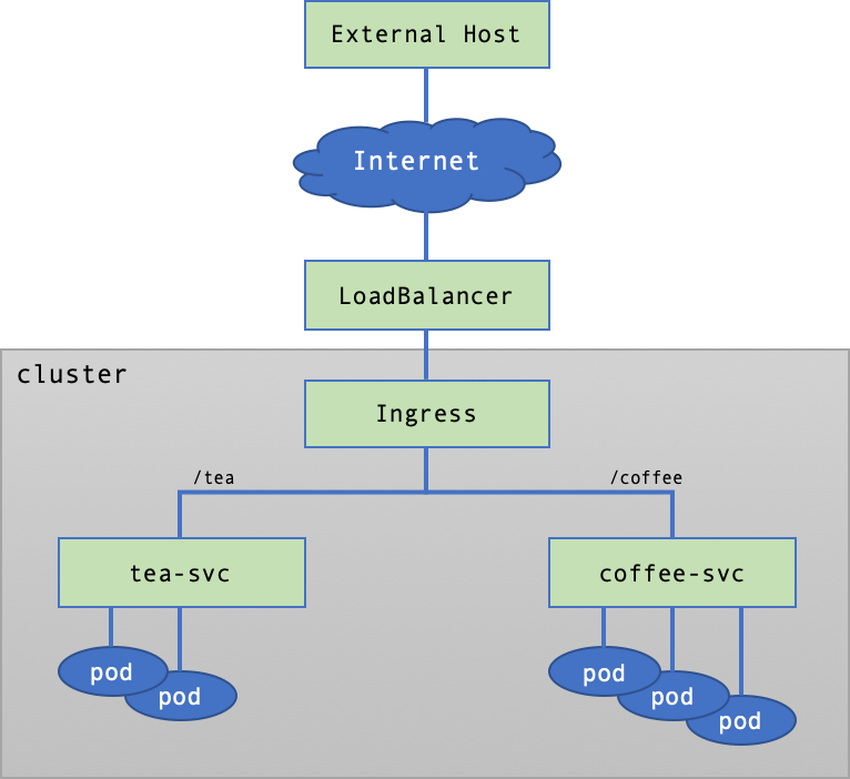
Create Services and Pods
Manifest is created to create services and pods like below: Associate the tea pod to tea-svc, and the coffee pod to coffee-svc.
# cafe.yaml
apiVersion: apps/v1
kind: Deployment
metadata:
  name: coffee
spec:
  replicas: 3
  selector:
    matchLabels:
      app: coffee
  template:
    metadata:
      labels:
        app: coffee
    spec:
      containers:
      - name: coffee
        image: nginxdemos/nginx-hello:plain-text
        ports:
        - containerPort: 8080
---
apiVersion: v1
kind: Service
metadata:
  name: coffee-svc
spec:
  ports:
  - port: 80
    targetPort: 8080
    protocol: TCP
    name: http
  selector:
    app: coffee
---
apiVersion: apps/v1
kind: Deployment
metadata:
  name: tea
spec:
  replicas: 2
  selector:
    matchLabels:
      app: tea
  template:
    metadata:
      labels:
        app: tea
    spec:
      containers:
      - name: tea
        image: nginxdemos/nginx-hello:plain-text
        ports:
        - containerPort: 8080
---
apiVersion: v1
kind: Service
metadata:
  name: tea-svc
  labels:
spec:
  ports:
  - port: 80
    targetPort: 8080
    protocol: TCP
    name: http
  selector:
    app: tea
Apply manifest, and see if deployment, service, and pod is created. The pod must be Running.
$ kubectl apply -f cafe.yaml
deployment.apps/coffee created
service/coffee-svc created
deployment.apps/tea created
service/tea-svc created

# kubectl get deploy,svc,pods
NAME                     READY   UP-TO-DATE   AVAILABLE   AGE
deployment.apps/coffee   3/3     3            3           27m
deployment.apps/tea      2/2     2            2           27m

NAME                 TYPE        CLUSTER-IP       EXTERNAL-IP   PORT(S)   AGE
service/coffee-svc   ClusterIP   10.254.171.198   <none>        80/TCP    27m
service/kubernetes   ClusterIP   10.254.0.1       <none>        443/TCP   5h51m
service/tea-svc      ClusterIP   10.254.184.190   <none>        80/TCP    27m

NAME                          READY   STATUS    RESTARTS   AGE
pod/coffee-7c86d7d67c-pr6kw   1/1     Running   0          27m
pod/coffee-7c86d7d67c-sgspn   1/1     Running   0          27m
pod/coffee-7c86d7d67c-tqtd6   1/1     Running   0          27m
pod/tea-5c457db9-fdkxl        1/1     Running   0          27m
pod/tea-5c457db9-z6hl5        1/1     Running   0          27m
Create Ingress
According to the request path, ingress manifest is created for service connection. A request with /tea as endpoint is connected to the tea-svc service, while /coffee is connected to the coffee-svc service.
# cafe-ingress-uri.yaml
apiVersion: networking.k8s.io/v1
kind: Ingress
metadata:
  name: cafe-ingress-uri
spec:
  ingressClassName: nginx
  rules:
  - http:
      paths:
      - path: /tea
        pathType: Prefix
        backend:
          service:
            name: tea-svc
            port:
              number: 80
      - path: /coffee
        pathType: Prefix
        backend:
          service:
            name: coffee-svc
            port:
              number: 80
In a while after ingress is created, IP must be configured at the ADDRESS field.
$ kubectl apply -f cafe-ingress-uri.yaml
ingress.networking.k8s.io/cafe-ingress-uri created

$ kubectl get ingress cafe-ingress-uri
NAME               CLASS   HOSTS   ADDRESS          PORTS   AGE
cafe-ingress-uri   nginx   *       123.123.123.44   80      23s
Send HTTP Requests
Send HTTP request to the IP address set for ADDRESS of ingress for an external host, to check if the ingress has been properly set.
Request for /coffee as endpoint is sent to the coffee-svc service so as the coffee pod can respond. From the Server Name, you can see that coffee pods take turns to respond in the round-robin technique.
$ curl 123.123.123.44/coffee
Server address: 10.100.24.21:8080
Server name: coffee-7c86d7d67c-sgspn
Date: 11/Mar/2022:06:28:18 +0000
URI: /coffee
Request ID: 3811d20501dbf948259f4b209c00f2f1

$ curl 123.123.123.44/coffee
Server address: 10.100.24.19:8080
Server name: coffee-7c86d7d67c-tqtd6
Date: 11/Mar/2022:06:28:27 +0000
URI: /coffee
Request ID: ec82f6ab31d622895374df972aed1acd

$ curl 123.123.123.44/coffee
Server address: 10.100.24.20:8080
Server name: coffee-7c86d7d67c-pr6kw
Date: 11/Mar/2022:06:28:31 +0000
URI: /coffee
Request ID: fec4a6111bcc27b9cba52629e9420076
Likewise, request for /tea as endpoint is delivered to the tea-svc service so as the tea can respond.
$ curl 123.123.123.44/tea
Server address: 10.100.24.23:8080
Server name: tea-5c457db9-fdkxl
Date: 11/Mar/2022:06:28:36 +0000
URI: /tea
Request ID: 11be1b7634a371a26e6bf2d3e72ab8aa
$ curl 123.123.123.44/tea
Server address: 10.100.24.22:8080
Server name: tea-5c457db9-z6hl5
Date: 11/Mar/2022:06:28:37 +0000
URI: /tea
Request ID: 21106246517263d726931e0f85ea2887
When a request is sent to undefined URI, the ingress controller sends 404 Not Found as response.
$ curl 123.123.123.44/unknown
<html>
<head><title>404 Not Found</title></head>
<body>
<center><h1>404 Not Found</h1></center>
<hr><center>nginx</center>
</body>
</html>
Delete Resources
Resources for testing can be deleted with used manifest.
$ kubectl delete -f cafe-ingress-uri.yaml
ingress.networking.k8s.io "cafe-ingress-uri" deleted

$ kubectl delete -f cafe.yaml
deployment.apps "coffee" deleted
service "coffee-svc" deleted
deployment.apps "tea" deleted
service "tea-svc" deleted
Service Divergence on Host
Ingress controller can diverge services based on the host name. The following figure shows the structure of a simple example of service divergence based on the host name.
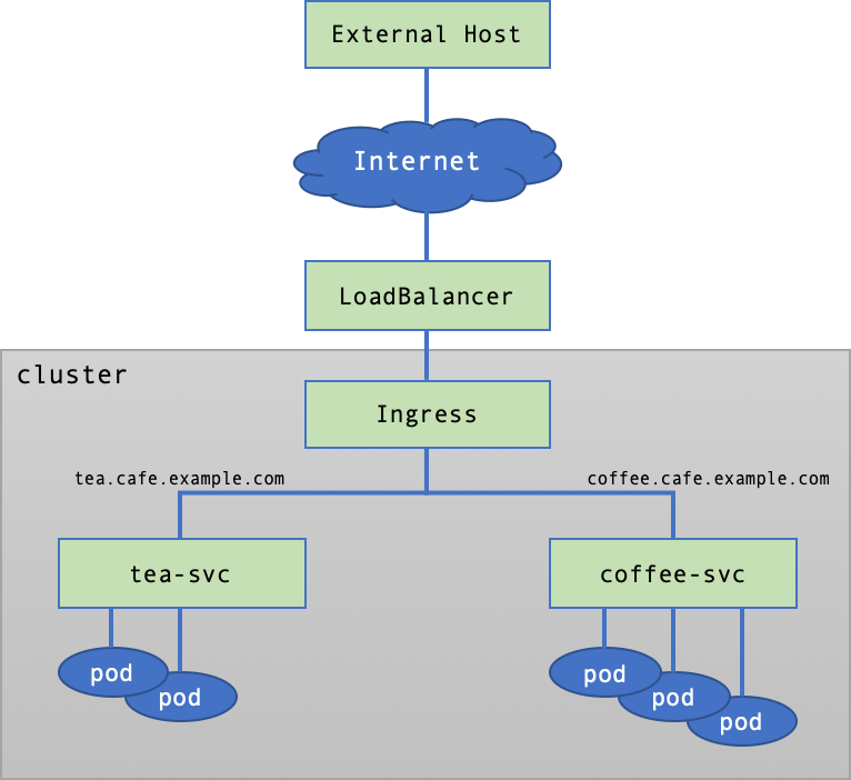
Create Services and Pods
Create services and pods by using the same manifest as URI-based Service Divergence.
Create Ingress
Write the ingress manifest connecting services based on the host name. Incoming request via the tea.cafe.example.com host is connected to the tea-svc service, while request via the coffee.cafe.example.com host is connected to the coffee-svc service.
# cafe-ingress-host.yaml
apiVersion: networking.k8s.io/v1
kind: Ingress
metadata:
  name: cafe-ingress-host
spec:
  ingressClassName: nginx
  rules:
  - host: tea.cafe.example.com
    http:
      paths:
      - path: /
        pathType: Prefix
        backend:
          service:
            name: tea-svc
            port:
              number: 80
  - host: coffee.cafe.example.com
    http:
      paths:
      - path: /
        pathType: Prefix
        backend:
          service:
            name: coffee-svc
            port:
              number: 80
In a while after ingress is created, IP must be configured at the ADDRESS field.
$ kubectl apply -f cafe-ingress-host.yaml
ingress.networking.k8s.io/cafe-ingress-host created

$ kubectl get ingress
NAME                CLASS   HOSTS                                          ADDRESS          PORTS   AGE
cafe-ingress-host   nginx   tea.cafe.example.com,coffee.cafe.example.com   123.123.123.44   80      36s
Send HTTP Requests
HTTP request is sent from external host to IP configured at the ADDRESS of the ingress controller. Nevertheless, such request must be sent by using host name, since service divergence is based on the host name by configuration.
[Note] To test with a random host name, use the --resolve option of curl: enter the --resolve option in the
{Host Name}:{Port Number}:{IP}format. This means to resolve a request for {Port Number} to be sent to {Host Name} as {IP}. You may open up the/etc/hostfile and add{IP} {Host Name}.
When a request is sent to the coffee.cafe.example.com host, it is delivered tocoffee-svc so that the coffee pod can respond.
$ curl --resolve coffee.cafe.example.com:80:123.123.123.44 http://coffee.cafe.example.com/
Server address: 10.100.24.27:8080
Server name: coffee-7c86d7d67c-fqn6n
Date: 11/Mar/2022:06:40:59 +0000
URI: /
Request ID: 1efb60d29891d6d48b5dcd9f5e1ba66d
When a request is sent to the tea.cafe.example.com host, it is delivered to tea-svc so that the tea pod can respond.
$ curl --resolve tea.cafe.example.com:80:123.123.123.44 http://tea.cafe.example.com/
Server address: 10.100.24.28:8080
Server name: tea-5c457db9-ngrxq
Date: 11/Mar/2022:06:41:39 +0000
URI: /
Request ID: 5a6cc490893636029766b02d2aab9e39
When it is requested to an unknown host, the ingress controller sends 404 Not Found as response.
$ curl 123.123.123.44/unknown
<html>
<head><title>404 Not Found</title></head>
<body>
<center><h1>404 Not Found</h1></center>
<hr><center>nginx</center>
</body>
</html>
Kubernetes Dashboard
NHN Kubernetes Service (NKS) provides the default web UI dashboard. For more details on Kubernetes Dashboard, see Web UI (Dashboard).
[Caution] * Kubernetes Dashboard supports up to NKS v1.25.4 by default. * If you upgrade your NKS cluster version from v1.25.4 to v1.26.3, the Kubernetes Dashboard pods and related resources will remain in action. * You can view Kubernetes resources from the NHN Cloud console.
Opening Dashboard Services
User Kubernetes has the kubernetes-dashboard service object which has been already created to publicly open dashboard.
$ kubectl get svc kubernetes-dashboard -n kube-system
NAME                   TYPE        CLUSTER-IP    EXTERNAL-IP   PORT(S)   AGE
kubernetes-dashboard   ClusterIP   10.254.85.2   <none>        443/TCP   6h

$ kubectl describe svc kubernetes-dashboard -n kube-system
Name:              kubernetes-dashboard
Namespace:         kube-system
Labels:            k8s-app=kubernetes-dashboard
Annotations:       <none>
Selector:          k8s-app=kubernetes-dashboard
Type:              ClusterIP
IP Family Policy:  SingleStack
IP Families:       IPv4
IP:                10.254.85.2
IPs:               10.254.85.2
Port:              <unset>  443/TCP
TargetPort:        8443/TCP
Endpoints:         10.100.24.7:8443
Session Affinity:  None
Events:            <none>
However, the kubernetes-dashboard object belongs to ClusterIP type and is not open out of the cluster. To open up dashboard externally, the service object type must be changed into LoadBalancer, or ingress controller and ingress object must be created.
Change into LoadBalancer
Once the type of service object is changed into LoadBalancer, NHN Cloud Load Balancer is created out of the cluster, which is associated with load balancer and service object. By querying service object associated with the load balancer, IP of the load balancer is displayed in the EXTERNAL-IP field. See LoadBalancer Service for the description of service objects of the LoadBalancer type. The following figure shows the structure of making dashboard public using the LoadBalancer type service.
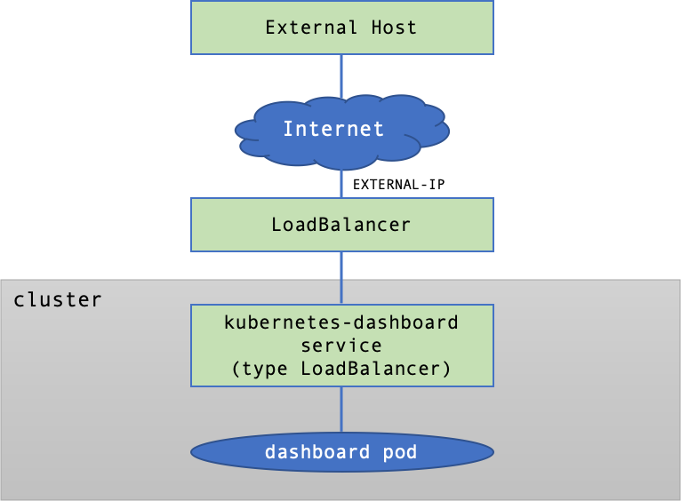
Change the type of the kubernetes-dashboard service object to LoadBalancer, like below:
$ kubectl -n kube-system patch svc/kubernetes-dashboard -p '{"spec":{"type":"LoadBalancer"}}'
service/kubernetes-dashboard patched
After the type of service object kubernetes-dashboard is changed to LoadBalancer, you can check load balancer IP from the EXTERNAL-IP field.
$ kubectl get svc -n kube-system
NAME                   TYPE           CLUSTER-IP      EXTERNAL-IP      PORT(S)                  AGE
...
kubernetes-dashboard   LoadBalancer   10.254.95.176   123.123.123.81   443:30963/TCP            2d23h
[Note] You can view the created load balancer on the Network > Load Balancer page. Load balancer IP is a floating IP allowing external access. You can check it on the Network > Floating IP page.
If you access https://{EXTERNAL-IP} in a web browser, the Kubernetes dashboard page is loaded. See Dashboard Access Token for the token required for login.
[Note] Since Kubernetes dashboard is based on a private certificate that is automatically created, the page may be displayed as unsafe, depending on the web browser or security setting.
Open Services with Ingress
Ingress refers to the network object providing routing to access many services within a cluster. The setting of an ingress object runs by ingress controller. The kubernetes-dashboard service object can go public through ingress. See Ingress Controller regarding description on ingress and ingress controller. The following figure shows the structure of making dashboard public through ingress.
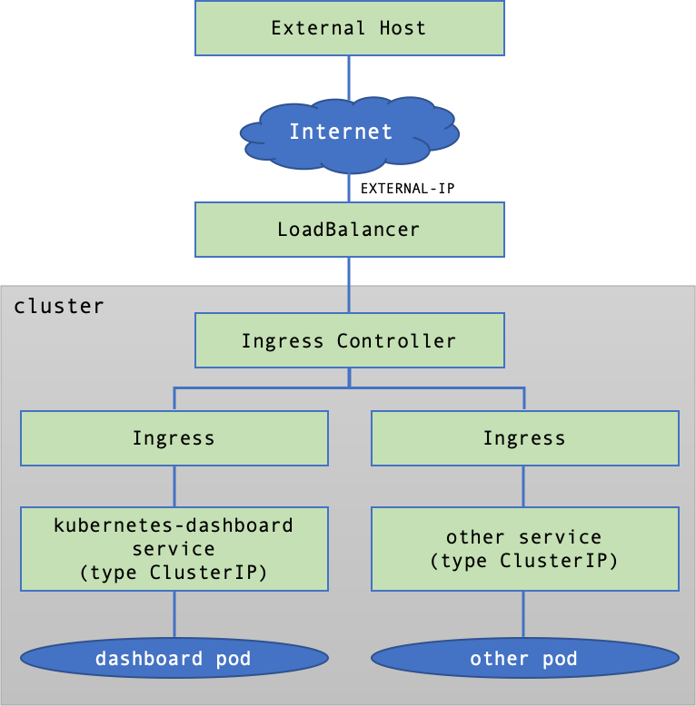
Install NGINX Ingress Controller by referring to Install NGINX Ingress Controller and write the manifest for creating an ingress object as follows.
# kubernetes-dashboard-ingress-tls-passthrough.yaml
apiVersion: networking.k8s.io/v1
kind: Ingress
metadata:
  name: k8s-dashboard-ingress
  namespace: kube-system
  annotations:
    ingress.kubernetes.io/ssl-passthrough: "true"
    kubernetes.io/ingress.allow-http: "false"
    nginx.ingress.kubernetes.io/backend-protocol: HTTPS
    nginx.ingress.kubernetes.io/proxy-body-size: 100M
    nginx.ingress.kubernetes.io/rewrite-target: /
    nginx.org/ssl-backend: kubernetes-dashboard
spec:
  ingressClassName: nginx
  rules:
  - http:
      paths:
      - path: /
        pathType: Prefix
        backend:
          service:
            name: kubernetes-dashboard
            port:
              number: 443
  tls:
  - secretName: kubernetes-dashboard-certs
Apply the manifest to create an ingress and check the ADDRESS field of the ingress object.
$ kubectl apply -f kubernetes-dashboard-ingress-tls-passthrough.yaml
ingress.networking.k8s.io/k8s-dashboard-ingress created

$ kubectl get ingress -n kube-system
NAME                    CLASS   HOSTS   ADDRESS          PORTS     AGE
k8s-dashboard-ingress   nginx   *       123.123.123.44   80, 443   34s
If you access https://{ADDRESS} in a web browser, the Kubernetes dashboard page is loaded. See Dashboard Access Token for the token required for login.
Dashboard Access Token
A token is required to log in to the Kubernetes dashboard. You can get the token with the following command:
# SECRET_NAME=$(kubectl -n kube-system get secrets | grep "kubernetes-dashboard-token" | cut -f1 -d ' ')

$ kubectl describe secret $SECRET_NAME -n kube-system | grep -E '^token' | cut -f2 -d':' | tr -d " "
eyJhbGc...-QmXA
Enter the printed token in the token input window on the browser, and you can log in as a user that has been granted the cluster admin privileges.
Persistent Volume
Persistent Volume or PV is a Kubernetes resource representing physical storage volume. One PV is attached to one NHN Cloud Block Storage. For more details, see Persistent Volume.
Persistent Volume Claims, or PVC is required to attach PV to pods. PVC defines necessary volume requirements, including volume and read/write modes.
With PV and PVC, user can define the attributes of a volume of choice, while the system seperates the use of resources from management by assigning volume resources for each user requirement.
Life Cycle of PV/PVC
PV and PVC support the four-phase life cycle.
-
Provisioning Using storage classes, users can manually secure a volume and create a PV (static provisioning) or dynamically create a PV (dynamic provisioning).
-
Binding Bind PV to PVC 1:1. With dynamic provisioning, binding is also automatically executed along with PV provisioning.
-
Using Mount PV to a pod to make it enabled.
-
Reclaiming Volume is reclaimed after it is used up, in three methods: Delete, Retain, or Recycle.
| Method | Description |
|---|---|
| Delete | PV is deleted along with its attached volumes. |
| Retain | PV is deleted but its attached volumes are not: volumes can be deleted or reused by user. |
| Recycle | PV is deleted and its attached volumes are made to be reused without being deleted. This method has been deprecated. |
Storage Class (StorageClass)
A storage class must be defined before provisioning. Storage classes provide a way to classify storages by certain characteristics. You can set the information such as media type and availability zone by including information about the storage provider (provisioner).
Storage Provider (provisioner)
Set the provider information of storage. Depending on the Kubernetes version, the supported storage provider information is as follows:
- v1.19.13 or earlier: The provisioner field must be set to
kubernetes.io/cinder. - v1.20.12 or later: You can use the provisioner field by setting it to
cinder.csi.openstack.org.
Parameters (parameter)
The storage class allows you to set the following parameters:
- Storage type (type): Enter the type of storage. (If not entered, General HDD is set.)
- General HDD: The storage type is set to HDD.
- General SSD: The storage type is set to SSD.
- Availability zone (availability): Set the availability zone. (If not entered, it will be set randomly.)
- Pangyo Region: kr-pub-a or kr-pub-b
- Pyeongchon region: kr2-pub-a or kr2-pub-b
Volume Binding Mode (VolumeBindingMode)
A volume binding mode controls the time when volume binding and dynamic provisioning start. This setting is configurable only if the storage provider is cinder.csi.openstack.org.
- Immediate: Volume binding and dynamic provisioning start as soon as a persistent volume claim is created. When the persistent volume claim is created, there is no prior knowledge of the pods to which the volume will be attached. Therefore, if the availability zone of the volume and the availability zone of the node on which the pod will be scheduled are different, the pod will not work properly.
- WaitForFirstConsumer: Volume binding and dynamic provisioning are not performed when a persistent volume claim is created. When this persistent volume claim is attached to a pod for the first time, volume binding and dynamic provisioning are performed based on the availability zone information of the node on which the pod is scheduled. Therefore, there is no case where the pod does not work properly because the availability zone of the volume and the availability zone of the instance are different, such as in Immediate mode.
Allow Volume Expansion (allowVolumeExpansion)
Set whether to allow expansion of the created volume (if not input, false is set).
- True : Volume expansion is allowed.
- False : Volume expansion is not allowed.
Example 1
The storage class manifest below can be used for Kubernetes clusters using v1.19.13 or earlier. You can use parameters to specify the availability zone and volume type.
# storage_class.yaml
apiVersion: storage.k8s.io/v1
kind: StorageClass
metadata:
  name: sc-ssd
provisioner: kubernetes.io/cinder
parameters:
  type: General SSD
  availability: kr-pub-a
Create the storage class and check that it has been created.
$ kubectl apply -f storage_class.yaml
storageclass.storage.k8s.io/sc-ssd created

$ kubectl get sc
NAME     PROVISIONER            RECLAIMPOLICY   VOLUMEBINDINGMODE   ALLOWVOLUMEEXPANSION   AGE
sc-ssd   kubernetes.io/cinder   Delete          Immediate           false                  3s
Example 2
The storage class manifest below can be used for Kubernetes clusters using v1.20.12 or later. Set the volume binding mode to WaitForFirstConsumer to initiate volume binding and dynamic provisioning when a persistent volume claim is attached to a pod.
# storage_class_csi.yaml
apiVersion: storage.k8s.io/v1
kind: StorageClass
metadata:
  name: csi-storageclass
provisioner: cinder.csi.openstack.org
volumeBindingMode: WaitForFirstConsumer
Create the storage class and check that it has been created.
$ kubectl apply -f storage_class_csi.yaml
storageclass.storage.k8s.io/csi-storageclass created

$ kubectl get sc
NAME               PROVISIONER                RECLAIMPOLICY   VOLUMEBINDINGMODE      ALLOWVOLUMEEXPANSION   AGE
csi-storageclass   cinder.csi.openstack.org   Delete          WaitForFirstConsumer   false                  7s
Static Provisioning
Static provisioning requires the user to prepare a block storage manually. On the Storage > Block Storage service page of the NHN Cloud web console, click the Create Block Storage button to create a block storage to attach to the PV. See Create Block Storage in the Block Storage guide.
To create a PV, you need the ID of the block storage. On the Storage > Block Storage service page, select the block storage you want to use from the block storage list. You can find the ID under the block storage name section in the Information tab at the bottom.
Write a manifest for the PV to be attached to the block storage. Enter the storage class name in spec.storageClassName. To use NHN Cloud Block Storage, spec.accessModes must be set to ReadWriteOnce. spec.presistentVolumeReclaimPolicy can be set to Delete or Retain.
Clusters in v1.20.12 and later must use the cinder.csi.openstack.org storage provider. To define the storage provider, specify the value pv.kubernetes.io/provisioned-by: cinder.csi. openstack. org under spec.annotations and the value driver: cinder.csi.openstack.org under csi entries.
[Caution] You must set a storage class in which the storage provider suitable for your Kubernetes version has been defined.
# pv-static.yaml
apiVersion: v1
kind: PersistentVolume
metadata:
  annotations:
    pv.kubernetes.io/provisioned-by:
cinder.csi.openstack.org
  name: pv-static-001
spec:
  capacity:
    storage: 10Gi
  volumeMode: Filesystem
  accessModes:
    - ReadWriteOnce
  persistentVolumeReclaimPolicy: Delete
  storageClassName: sc-default
  csi:
    driver: cinder.csi.openstack.org
    fsType: "ext3"
    volumeHandle: "e6f95191-d58b-40c3-a191-9984ce7532e5" # UUID of Block Storage
Create the PV and check that it has been created.
$ kubectl apply -f pv-static.yaml
persistentvolume/pv-static-001 created

$ kubectl get pv -o wide
NAME            CAPACITY   ACCESS MODES   RECLAIM POLICY   STATUS      CLAIM   STORAGECLASS   REASON   AGE   VOLUMEMODE
pv-static-001   10Gi       RWO            Delete           Available           sc-default              7s    Filesystem
Write a PVC manifest to use the created PV. The PV name must be specified in spec.volumeName. Set other items the same as PV manifest.
# pvc-static.yaml
apiVersion: v1
kind: PersistentVolumeClaim
metadata:
  name: pvc-static
  namespace: default
spec:
  volumeName: pv-static-001
  accessModes:
  - ReadWriteOnce
  resources:
    requests:
      storage: 10Gi
  storageClassName: sc-default
Create and check PVC.
$ kubectl apply -f pvc-static.yaml
persistentvolumeclaim/pvc-static created

$ kubectl get pvc -o wide
NAME         STATUS   VOLUME          CAPACITY   ACCESS MODES   STORAGECLASS   AGE   VOLUMEMODE
pvc-static   Bound    pv-static-001   10Gi       RWO            sc-default     7s    Filesystem
After the PVC is created, query PV status, and you can find PVC name specified for CLAIM and STATUS changed into Bound.
$ kubectl get pv -o wide
NAME            CAPACITY   ACCESS MODES   RECLAIM POLICY   STATUS   CLAIM                STORAGECLASS   REASON   AGE   VOLUMEMODE
pv-static-001   10Gi       RWO            Delete           Bound    default/pvc-static   sc-default              79s   Filesystem
Dynamic Provisioning
With Dynamic Provisioning, block storage is automatically created in reference of attributes defined at storage class. To use Dynamic Provisioning, do not set Volume Binding Mode of storage class or set it to Immediate.
# storage_class_csi_dynamic.yaml
apiVersion: storage.k8s.io/v1
kind: StorageClass
metadata:
  name: csi-storageclass-dynamic
provisioner: cinder.csi.openstack.org
volumeBindingMode: Immediate
There is no need to create PV for dynamic provisioning; therefore, PVC manifest does not require the setting of spec.volumeName.
# pvc-dynamic.yaml
apiVersion: v1
kind: PersistentVolumeClaim
metadata:
  name: pvc-dynamic
  namespace: default
spec:
  accessModes:
  - ReadWriteOnce
  resources:
    requests:
      storage: 10Gi
  storageClassName: csi-storageclass-dynamic
If you do not set the volume binding mode or set it to Immediate and create a PVC, the PV will be created automatically. At the same time, block storage attached to the PV is also automatically created, and you can check it from the list of block storages on the Storage > Block Storage page of the NHN Cloud web console.
$ kubectl apply -f pvc-dynamic.yaml
persistentvolumeclaim/pvc-dynamic created

$ kubectl get sc,pv,pvc
NAME                                                   PROVISIONER                RECLAIMPOLICY   VOLUMEBINDINGMODE   ALLOWVOLUMEEXPANSION   AGE
storageclass.storage.k8s.io/csi-storageclass-dynamic   cinder.csi.openstack.org   Delete          Immediate           false                  50s

NAME                                                        CAPACITY   ACCESS MODES   RECLAIM POLICY   STATUS   CLAIM                 STORAGECLASS               REASON   AGE
persistentvolume/pvc-1056949c-bc67-45cc-abaa-1d1bd9e51467   10Gi       RWO            Delete           Bound    default/pvc-dynamic   csi-storageclass-dynamic            5s

NAME                                STATUS   VOLUME                                     CAPACITY   ACCESS MODES   STORAGECLASS               AGE
persistentvolumeclaim/pvc-dynamic   Bound    pvc-1056949c-bc67-45cc-abaa-1d1bd9e51467   10Gi       RWO            csi-storageclass-dynamic   9s
[Caution] A block storage created by dynamic provisioning cannot be deleted from the web console. It is not automatically deleted along with a cluster being deleted. Therefore, before a cluster is deleted, all PVCs must be deleted first; otherwise, you may be charged for PVC usage. The reclaimPolicy of PV created by dynamic provisioning is set to
Deleteby default, so deleting only the PVC will also delete the PV and block storage.
Mounting PVC to Pods
To mount PVC to a pod, mount information must be defined at the pod manifest. Enter the PVC name to use in spec.volumes.persistenVolumeClaim.claimName; enter paths to mount in spec.containers.volumeMounts.mountPath.
In the following example, a PVC created with static provisioning is mounted to /usr/share/nginx/html of the pod.
# pod-pvc.yaml
apiVersion: v1
kind: Pod
metadata:
  name: nginx-with-static-pv
spec:
  containers:
    - name: web
      image: nginx
      ports:
        - name: web
          containerPort: 80
          hostPort: 8082
          protocol: TCP
      volumeMounts:
        - name: html-volume
          mountPath: "/usr/share/nginx/html"
  volumes:
    - name: html-volume
      persistentVolumeClaim:
        claimName: pvc-static
Create the pod and see if the block storage has been mounted.
$ kubectl apply -f pod-static-pvc.yaml
pod/nginx-with-static-pv created

$ kubectl get pods
NAME                   READY   STATUS    RESTARTS   AGE
nginx-with-static-pv   1/1     Running   0          50s

$ kubectl exec -ti nginx-with-static-pv -- df -h
Filesystem      Size  Used Avail Use% Mounted on
...
/dev/vdc        9.8G   23M  9.7G   1% /usr/share/nginx/html
...
You can also check block storage attachment information in the Storage > Block Storage service page of the NHN Cloud web console.
Volume Expansion
You can adjust an existing volume by editing the PersistentVolumeClaim (PVC) object. You can change the volume size by editing the spec.resources.requests.storage item of the PVC object. Volume shrinking is not supported. To use the volume expansion feature, the allowVolumeExpansion property of StorageClass must be True.
Volume Expansion from v1.19.13 and older
kubernetes.io/cinder, the storage provider from v1.19.13 and older does not provide the volume expansion feature for the volume in use. To use the feature for the volume in use, you must use cinder.csi.openstack.org, the storage provider from v1.20.12 and later. The cluster upgrade feature allows you to upgrade the version to v1.20.12 or later in order to use the storage provider cinder.csi.openstack.org.
To use the storage provider cinder.csi.openstack.orgfrom v1.20.12 and older instead of the storage provider kubernetes.io/cinder from v1.19.13 and older, you must modify the annotations of PVC as follows.
- pv.kubernetes.io/bind-completed: "yes" > Delete
- pv.kubernetes.io/bound-by-controller: "yes" > Delete
- volume.beta.kubernetes.io/storage-provisioner: kubernetes.io/cinder > volume.beta.kubernetes.io/storage-provisioner:cinder.csi.openstack.org
- volume.kubernetes.io/storage-resizer: kubernetes.io/cinder > volume.kubernetes.io/storage-resizer: cinder.csi.openstack.org
- pv.kubernetes.io/provisioned-by:cinder.csi.openstack.org > Add
Below is a modified PVC example.
apiVersion: v1
kind: PersistentVolumeClaim
metadata:
  annotations:
    pv.kubernetes.io/provisioned-by: cinder.csi.openstack.org
    volume.beta.kubernetes.io/storage-provisioner: cinder.csi.openstack.org
    volume.kubernetes.io/storage-resizer: cinder.csi.openstack.org
  creationTimestamp: "2022-07-18T06:13:01Z"
  finalizers:
  - kubernetes.io/pvc-protection
  labels:
    app: nginx
  name: www-web-0
  namespace: default
spec:
  accessModes:
  - ReadWriteOnce
  resources:
    requests:
      storage: 310Gi
  storageClassName: sc-ssd
  volumeMode: Filesystem
  volumeName: pvc-0da7cd55-bf29-4597-ab84-2f3d46391e5b
status:
  accessModes:
  - ReadWriteOnce
  capacity:
    storage: 300Gi
  phase: Bound
Volume Expansion from v1.20.12 and older
The storage provider cinder.csi.openstack.org from v1.20.12 and later supports the expansion of the volume in use by default. You can change the volume size by modifying the spec.resources.requests.storage item of the PVC object to a desired value.
Integrate with NHN Cloud Service
Integrate with NHN Cloud Container Registry (NCR)
You can use images saved at NHN Cloud Container Registry. To use images registered in the registry, first create a secret to login to user registry.
To use NHN Cloud (Old) Container Registry, you need to create a secret as follows:
$ kubectl create secret docker-registry registry-credential --docker-server={user registry address} --docker-username={email address for NHN Cloud account} --docker-password={service Appkey or integrated Appkey}
secret/registry-credential created

$ kubectl get secrets
NAME                  TYPE                             DATA   AGE
registry-credential   kubernetes.io/dockerconfigjson   1      30m
To use NHN Cloud Container Registry, you need to create a secret as follows:
$ kubectl create secret docker-registry registry-credential --docker-server={User registry address} --docker-username={User Access Key ID} --docker-password={Secret Access Key}
secret/registry-credential created

$ kubectl get secrets
NAME                  TYPE                             DATA   AGE
registry-credential   kubernetes.io/dockerconfigjson   1      30m
By adding secret information to the deployment manifest file and changing the name of image, pods can be created by using images saved at user registry.
# nginx.yaml
...
spec:
  ...
  template:
    ...
    spec:
      containers:
      - name: nginx
        image: {User registry address}/nginx:1.14.2
        ...
      imagePullSecrets:
      - name: registry-credential
[Note] Regarding how to use NHN Cloud Container Registry, see NHN Cloud Container Registry (NCR) User Guide.
Integrate with NHN Cloud NAS
You can utilize NAS storage provided by NHN Cloud as PV. In order to use NAS services, you must use a cluster of version v1.20 or later. For more information on using NHN Cloud NAS, please refer to the NAS Console User Guide.
[Note] The NHN Cloud NAS service is currently (2024.02) only available in some regions. For more information on supported regions for NHN Cloud NAS service, see NAS Service Overview.
Run the rpcbind service on All Worker Nodes
To use NAS storage, you must run the rpcbind service on all worker nodes. After connecting to all worker nodes, run the rpcbind service with the command below.
The command to run the rpcbind service is the same regardless of the image type.
$ systemctl start rpcbind
For clusters that are using enforced security rules, you must add security rules.
| Direction | IP protocol | Port range | Ether | Remote | Description |
|---|---|---|---|---|---|
| egress | TCP | 2049 | IPv4 | NAS IP address | NFS port in rpc, direction: csi-nfs-node(worker node) -> NAS |
| egress | TCP | 111 | IPv4 | NAS IP address | portmapper port in rpc, direction: csi-nfs-node(worker node) -> NAS |
| egress | TCP | 635 | IPv4 | NAS IP address | rpc's mountd port, direction: csi-nfs-node(worker node) -> NAS |
Install csi-driver-nfs
To use the NHN Cloud NAS service, you must deploy the csi-driver-nfs components.
csi-driver-nfs is a driver that supports NFS storage provisioning that works by creating new subdirectories on NFS storage. csi-driver-nfs works by presenting NFS storage information to storage classes, reducing what you have to manage.
If you configure multiple PVs using the nfs-csi-driver, the nfs-csi-driver registers the NFS storage information in the StorageClass, removing the need to configure an NFS-Provisioner pod.
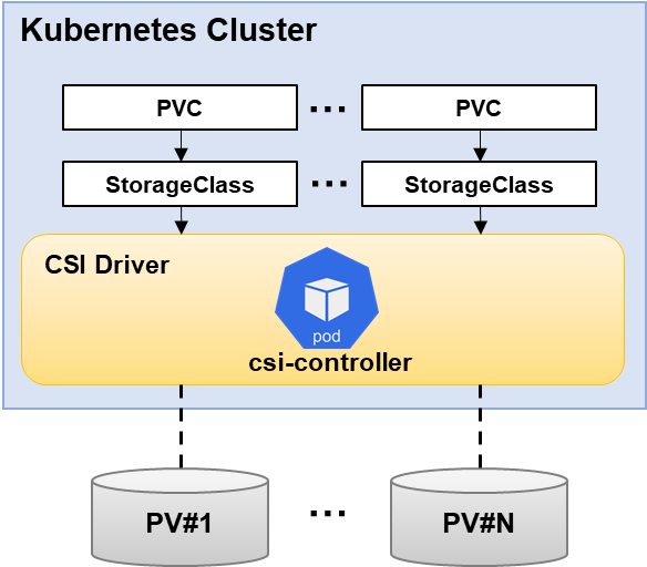
[Note] During the internal execution of the csi-driver-nfs execution script, the kubectl apply command is performed. Therefore, the installation should proceed with the
kubectlcommand operating normally. The csi-driver-nfs installation process is based on the Linux environment.
1. Save the absolute path of a cluster configuration file in an environment variable.
$ export KUBECONFIG={Absolute path of a cluster configruration file}
ORAS (OCI Registry As Storage) is a tool that provides a way to push and pull OCI artifacts from an OCI registry. Refer to ORAS installation to install ORAS command line tools. For detailed usage of the ORAS command line tools, see the ORAS docs.
| Region | Internet Connection | Download Command |
|---|---|---|
| Korea (Pangyo) region | O | oras pull dfe965c3-kr1-registry.container.nhncloud.com/container_service/oci/nfs-deploy-tool:v1 |
| X | oras pull private-dfe965c3-kr1-registry.container.nhncloud.com/container_service/oci/nfs-deploy-tool:v1 | |
| Korea (Pyengchon) region | O | oras pull 6e7f43c6-kr2-registry.container.cloud.toast.com/container_service/oci/nfs-deploy-tool:v1 |
| X | oras pull private-6e7f43c6-kr2-registry.container.cloud.toast.com/container_service/oci/nfs-deploy-tool:v1 |
3. After unzipping the installation package, install the csi-driver-nfs component using the install-driver.sh {mode} command.
When you run the install-driver.sh command, you must enter public for clusters that can connect to the Internet, and private for clusters that do not.
[Note] The csi-driver-nfs container image is maintained in NHN Cloud NCR. Since the cluster configured in a closed network environment is not connected to the Internet, it is necessary to configure the environment to use a private URI in order to receive images normally. For information on how to use Private URI, refer to the NHN Cloud Container Registry (NCR) User Guide.
Below is an example of installing csi-driver-nfs using the installation package in the cluster configured in the Internet network environment.
$ tar -xvf nfs-deploy-tool.tar

$ ./install-driver.sh public
Installing NFS CSI driver, mode: public ...
serviceaccount/csi-nfs-controller-sa created
serviceaccount/csi-nfs-node-sa created
clusterrole.rbac.authorization.k8s.io/nfs-external-provisioner-role created
clusterrolebinding.rbac.authorization.k8s.io/nfs-csi-provisioner-binding created
csidriver.storage.k8s.io/nfs.csi.k8s.io created
deployment.apps/csi-nfs-controller created
daemonset.apps/csi-nfs-node created
NFS CSI driver installed successfully.
4. Check that the components are installed properly.
$ kubectl get pods -n kube-system
NAMESPACE     NAME                                         READY   STATUS    RESTARTS   AGE
kube-system   csi-nfs-controller-844d5989dc-scphc          3/3     Running   0          53s
kube-system   csi-nfs-node-hmps6                           3/3     Running   0          52s

$ kubectl get clusterrolebinding
NAME                                                                                                ROLE                                                               AGE
clusterrolebinding.rbac.authorization.k8s.io/nfs-csi-provisioner-binding                            ClusterRole/nfs-external-provisioner-role                          52s

$ kubectl get clusterrole
NAME                                                                                                         CREATED AT
clusterrole.rbac.authorization.k8s.io/nfs-external-provisioner-role                                          2022-08-09T06:21:20Z

$ kubectl get csidriver
NAME                                                ATTACHREQUIRED   PODINFOONMOUNT   MODES                  AGE
csidriver.storage.k8s.io/nfs.csi.k8s.io             false            false            Persistent,Ephemeral   47s

$ kubectl get deployment -n kube-system
NAMESPACE     NAME                        READY   UP-TO-DATE   AVAILABLE   AGE
kube-system   coredns                     2/2     2            2           22d
kube-system   csi-nfs-controller          1/1     1            1           4m32s

$ kubectl get daemonset -n kube-system
NAMESPACE     NAME                    DESIRED   CURRENT   READY   UP-TO-DATE   AVAILABLE   NODE SELECTOR                   AGE
kube-system   csi-nfs-node            1         1         1       1            1           kubernetes.io/os=linux          4m23s
How to Use existing NHN Cloud NAS Storage When Provisioning
You can use existing NAS storage as a PV by entering the NAS information when creating the PV manifest or by entering the NAS information in the StorageClass manifest.
Method 1. Define NAS storage information when creating a PV manifest
When creating the PV manifest, you must define the NHN Cloud NAS Storage information. The setting location is csi under .spec.
- driver: Enter nfs.csi.k8s.io
- readOnly: Enter false
- volumeHandle: Enter a unique, non-duplicate id within the cluster.
- volumeAttributes: Enter connection information for NAS storage.
- server: Enter the value of the ip part of the NAS storage connection information.
- share: Enter the value of the volume name part of the NAS storage connection information.
Below is an example manifest.
# pv.yaml
apiVersion: v1
kind: PersistentVolume
metadata:
  name: pv-onas
spec:
  capacity:
    storage: 300Gi
  accessModes:
    - ReadWriteMany
  persistentVolumeReclaimPolicy: Retain
  csi:
    driver: nfs.csi.k8s.io
    readOnly: false
    volumeHandle: unique-volumeid
    volumeAttributes:
      server: 192.168.0.98
      share: /onas_300gb
Create the PV and check that it has been created.
$ kubectl apply -f pv.yaml
persistentvolume/pv-onas created

$ kubectl get pv -o wide
NAME                                       CAPACITY   ACCESS MODES   RECLAIM POLICY   STATUS      CLAIM                      STORAGECLASS   REASON   AGE    VOLUMEMODE
pv-onas                                    300Gi      RWX            Retain           Available                                                      101s   Filesystem
Write a PVC manifest to use the created PV. The PV name must be specified in spec.volumeName. Set other items the same as PV manifest.
# pvc.yaml
kind: PersistentVolumeClaim
apiVersion: v1
metadata:
  name: pvc-onas
spec:
  accessModes:
    - ReadWriteMany
  resources:
    requests:
      storage: 300Gi
  volumeName: pv-onas
Create and check PVC.
$ kubectl apply -f pvc.yaml
persistentvolumeclaim/pvc-onas created

$ kubectl get pvc -o wide
NAME              STATUS   VOLUME    CAPACITY   ACCESS MODES   STORAGECLASS   AGE    VOLUMEMODE
pvc-onas   Bound    pv-onas   300Gi      RWX                           2m8s   Filesystem
If you create a PVC and then check the status of the PV, you can see that the CLAIM entry is specified with the PVC name and the STATUS entry is changed to Bound.
$ kubectl get pv -o wide
NAME      CAPACITY   ACCESS MODES   RECLAIM POLICY   STATUS   CLAIM                     STORAGECLASS   REASON   AGE     VOLUMEMODE
pv-onas   300Gi      RWX            Retain           Bound    default/pvc-onas                           3m20s   Filesystem
Method 2. Define NAS information when creating a StorageClass manifest
Define Storage provider information and NHN Cloud NAS storage information when the StorageClass manifest is created.
- provisioner: Enternfs.csi.k8s.io.
- parameters: Enter the connection information of the NAS storage.
- server: Enter the value of the ip part of the NAS storage connection information.
- share: Enter the value of the volume name part of the NAS storage connection information.
Below is an example manifest.
# storageclass.yaml
apiVersion: storage.k8s.io/v1
kind: StorageClass
metadata:
  name: onas-sc
provisioner: nfs.csi.k8s.io
parameters:
  server: 192.168.0.81
  share: /onas_300gb
reclaimPolicy: Retain
volumeBindingMode: Immediate
Create and check StorageClass.
$ kubectl apply -f storageclass.yaml
storageclass.storage.k8s.io/onas-sc created

$ kubectl get sc
NAME      PROVISIONER      RECLAIMPOLICY   VOLUMEBINDINGMODE   ALLOWVOLUMEEXPANSION   AGE
onas-sc   nfs.csi.k8s.io   Retain          Immediate           false                  3s
There is no need to create PV and create PVC manifest. PVC manifest does not require the setting of spec.volumeName.
# pvc.yaml
kind: PersistentVolumeClaim
apiVersion: v1
metadata:
  name: pvc-onas-dynamic
spec:
  accessModes:
    - ReadWriteMany
  resources:
    requests:
      storage: 300Gi
  storageClassName: onas-sc
If you do not set the volume binding mode or set it to Immediate and create a PVC, the PV will be created automatically.
$ kubectl apply -f pvc.yaml
persistentvolumeclaim/pvc-onas created

$ kubectl get sc,pv,pvc
NAME                                  PROVISIONER      RECLAIMPOLICY   VOLUMEBINDINGMODE   ALLOWVOLUMEEXPANSION   AGE
storageclass.storage.k8s.io/onas-sc   nfs.csi.k8s.io   Retain          Immediate           false                  25s

NAME                                                        CAPACITY   ACCESS MODES   RECLAIM POLICY   STATUS   CLAIM                      STORAGECLASS   REASON   AGE
persistentvolume/pvc-71392e58-5d8e-43b2-9798-5b59de34b203   300Gi      RWX            Retain           Bound    default/pvc-onas   onas-sc                 3s

NAME                                     STATUS   VOLUME                                     CAPACITY   ACCESS MODES   STORAGECLASS   AGE
persistentvolumeclaim/pvc-onas   Bound    pvc-71392e58-5d8e-43b2-9798-5b59de34b203   300Gi      RWX            onas-sc        4s
To mount PVC to a pod, mount information must be defined at the pod manifest. Enter the PVC name to use in spec.volumes.persistenVolumeClaim.claimName and enter paths to mount in spec.containers.volumeMounts.mountPath.
Below is an example manifest that mounts the PVC you created into the pod's /tmp/nfs.
# deployment.yaml
apiVersion: apps/v1
kind: Deployment
metadata:
  labels:
    app: nginx
  name: nginx
  namespace: default
spec:
  selector:
    matchLabels:
      app: nginx
  template:
    metadata:
      labels:
        app: nginx
    spec:
      containers:
      - image: nginx
        imagePullPolicy: Always
        name: nginx
        volumeMounts:
          - name: onas-dynamic
            mountPath: "/tmp/nfs"
      volumes:
        - name: onas-dynamic
          persistentVolumeClaim:
            claimName: pvc-onas-dynamic
Create the pod and make sure the NAS storage is mounted.
$ kubectl apply -f deployment.yaml
deployment.apps/nginx created

$ kubectl get pods
NAME                             READY   STATUS    RESTARTS   AGE
nginx-5fbc846574-q28cf   1/1     Running   0          26s

$ kubectl exec -it nginx-5fbc846574-q28cf -- df -h
Filesystem                                                                 Size  Used Avail Use% Mounted on
...
192.168.0.45:/onas_300gb/pvc-71392e58-5d8e-43b2-9798-5b59de34b203  270G  256K  270G   1% /tmp/nfs
...
How to create new NHN Cloud NAS storage when provisioning
You can use the automatically created NAS storage as a PV by entering the NAS information when creating the StorageClass and PVC manifest.
In the StorageClass manifest, define the storage provider information, snapshot policy, access control list (ACL), and subnet information of the NAS storage to be created. * provisioner: Enternfs.csi.k8s.io. * parameters: Refer to the table below for input items. If multiple values are defined in the parameter value, use **,** to separate the values.
| Item | Description | Example | Multi Value | Required | Default |
|---|---|---|---|---|---|
| maxscheduledcount | The maximum number of snapshots that can be stored. When the maximum number of saves is reached, the first automatically created snapshot is deleted. Only numbers between 1 and 20 can be entered. | "7" | X | X | |
| reservepercent | The maximum snapshot storage capacity. If the total amount of snapshot capacity exceeds the set size, the snapshot created first among all snapshots is deleted. Only numbers between 0 and 80 can be entered. | "80" | X | X | |
| scheduletime | The time at which the snapshot will be created. | X | X | ||
| scheduletimeoffset | Offset to the snapshot creation time. It is based on UTC, and when used in KST, specify +09:00 value. | "+09:00" | X | X | |
| scheduleweekdays | Snapshot creation cycle. Sunday through Saturday are represented by the numbers 0 through 6, respectively. | "6" | O | X | |
| subnet | The subnet to access the storage. Only subnets in the selected VPC can be chosen. | "59526f1c-c089-4517-86fd-2d3dac369210" | X | O | |
| acl | A list of the IPs or CIDR blocks that allow read and write permissions. | "0.0.0.0/0" | O | X | 0.0.0.0/0 |
| onDelete | Whether to delete the NAS volume when deleting PVC. | "delete" / "retain" | X | X | delete |
[Note] When using snapshot parameters, all relevant parameter values must be defined. Snapshot related parameters are as follows. + maxscheduledcount + reservepercent + scheduletime + scheduletimeoffset + scheduleweekdays
[Caution] Limitations in multi-subnet environments
NAS storage is attached to the subnet defined in the storage class. To integrate pods with NAS storage, all worker node groups must be connected to the subnet.
Below is an example manifest.
# storage_class.yaml
apiVersion: storage.k8s.io/v1
kind: StorageClass
metadata:
  name: sc-nfs
provisioner: nfs.csi.k8s.io
reclaimPolicy: Delete
volumeBindingMode: Immediate
parameters:
  maxscheduledcount : "7"
  reservepercent : "80"
  scheduletime : "09:00"
  scheduletimeoffset : "+09:00"
  scheduleweekdays : "6"
  subnet : "59526f1c-c089-4517-86fd-2d3dac369210"
  acl : ""
Define the name, description, and size of the NAS storage to be created in the Annotation of the PVC manifest. Refer to the table below for input items.
| Item | Description | Example | Required |
|---|---|---|---|
| nfs-volume-name | Name of the storage to be created. The NFS access path can be created with the storage name. Storage name is limited to less than 100 alphabetic characters, numbers, and some symbols ('-', '_'). | "nas_sample_volume_300gb" | O |
| nfs-volume-description | A description of the NAS storage to create. | "nas sample volume" | X |
| nfs-volume-sizegb | The size of NAS storage to create. It is set in GB unit. It can be entered from a minimum of 300 to a maximum of 10,000. | "300" | O |
Below is an example manifest.
# pvc.yaml
apiVersion: v1
kind: PersistentVolumeClaim
metadata:
  name: pvc-nfs
  annotations:
    nfs-volume-name: "nas_sample_volume_300gb"
    nfs-volume-description: "nas sample volume"
    nfs-volume-sizegb: "300"
spec:
  accessModes:
    - ReadWriteMany
  resources:
    requests:
      storage: 50Gi
  storageClassName: sc-nfs
Create and verify StorageClass and PVC.
$ kubectl apply -f storage_class.yaml
storageclass.storage.k8s.io/sc-nfs created

$ kubectl get sc
NAME         PROVISIONER      RECLAIMPOLICY   VOLUMEBINDINGMODE   ALLOWVOLUMEEXPANSION   AGE
sc-nfs       nfs.csi.k8s.io   Delete          Immediate           false                  50s
You don't need to create a PV separately, just create a PVC manifest. Do not set spec.volumeName in the PVC manifest. If you do not set the volume binding mode or set it to Immediate and create a PVC, the PV will be created automatically. After the NAS storage is created, it takes about 1 minute to be bound. You can also check the created NAS storage information on the Storage > NAS Service page in the NHN Cloud console.
$ kubectl apply -f pvc.yaml
persistentvolumeclaim/pvc-nfs created

$ kubectl get pv,pvc
NAME                                                        CAPACITY   ACCESS MODES   RECLAIM POLICY   STATUS   CLAIM             STORAGECLASS   REASON   AGE
persistentvolume/pvc-a8ea2054-0849-4fe8-8207-ee0e43b8a103   50Gi       RWX            Delete           Bound    default/pvc-nfs   sc-nfs                  2s

NAME                            STATUS   VOLUME                                     CAPACITY   ACCESS MODES   STORAGECLASS   AGE
persistentvolumeclaim/pvc-nfs   Bound    pvc-a8ea2054-0849-4fe8-8207-ee0e43b8a103   50Gi       RWX            sc-nfs         75s
To mount PVC to a pod, mount information must be defined at the pod manifest. Enter the PVC name to use in spec.volumes.persistenVolumeClaim.claimName and enter paths to mount in spec.containers.volumeMounts.mountPath.
Below is an example manifest that mounts a PVC created to /tmp/nfs in a Pod.
# deployment.yaml
apiVersion: apps/v1
kind: Deployment
metadata:
  labels:
    app: nginx
  name: nginx
  namespace: default
spec:
  selector:
    matchLabels:
      app: nginx
  template:
    metadata:
      labels:
        app: nginx
    spec:
      containers:
      - image: nginx
        imagePullPolicy: Always
        name: nginx
        volumeMounts:
          - name: nas
            mountPath: "/tmp/nfs"
      volumes:
        - name: nas
          persistentVolumeClaim:
            claimName: pvc-nfs
Create the pod and make sure the NAS storage is mounted.
$ kubectl apply -f deployment.yaml
deployment.apps/nginx created

$ kubectl get pods
NAME                             READY   STATUS    RESTARTS   AGE
nginx-9f448b9f7-xw92w   1/1     Running   0          12s

$ kubectl exec -it nginx-9f448b9f7-xw92w -- df -h
Filesystem                                                                     Size  Used Avail Use% Mounted on
overlay                                                                         20G   16G  4.2G  80% /
tmpfs                                                                           64M     0   64M   0% /dev
tmpfs                                                                          1.9G     0  1.9G   0% /sys/fs/cgroup
192.168.0.57:nas_sample_volume_100gb/pvc-a8ea2054-0849-4fe8-8207-ee0e43b8a103   20G  256K   20G   1% /tmp/nfs
...
[Note] csi-driver-nfsworks by creating a subdirectory inside the NFS storage when provisioning. In the process of mounting the PV to the pod, not only the subdirectory is mounted, but the entire nfs storage is mounted, so it is not possible to force the application to use the volume by the provisioned size.
NHN Cloud Encrypted Block Storage Integration
You can utilize encrypted block storage provided by NHN Cloud as PV. For more information about NHN Cloud encrypted block storage, see Encrypted Block Storage.
[Note] The Encrypted Block Storage service integration is available for clusters in v1.24.3 and later versions. Newly created clusters on or after November 28, 2023 have the Encrypted Block Storage integration feature built in by default. Clusters created before November 28, 2023 can enable encrypted block storage integration by upgrading to v1.24.3 or later, or by replacing the cinder-csi-plugin images in the csi-cinder-controllerplugin statefulset and csi-cinder-nodeplugin daemonset with newer versions.
[Caution] If you are using a cluster with a version prior to v1.24.3 without upgrading it and just replacing the cinder-csi-plugin container image, it can cause malfunctions.
Updating cinder-csi-plugin image for encrypted block storage integration
You can run the command below to see the tags of the cinder-csi-plugin images currently deployed in your cluster.
$ kubectl -n kube-system get statefulset csi-cinder-controllerplugin -o=jsonpath="{$.spec.template.spec.containers[?(@.name=='cinder-csi-plugin')].image}"

> registry.k8s.io/provider-os/cinder-csi-plugin:v1.27.101
If the tag in the cinder-csi-plugin image is v1.27.101 or later, you can integrate encrypted block storage without taking any action. If the tag of the cinder-csi-plugin image is less than v1.27.101, you can update the image of the cinder-csi-plugin using the steps below and then integrate encrypted block storage.
| Region | Internet Connection | cinder-csi-plugin image |
|---|---|---|
| Korea (Pangyo) region | O | dfe965c3-kr1-registry.container.nhncloud.com/container_service/cinder-csi-plugin:v1.27.101 |
| X | private-dfe965c3-kr1-registry.container.nhncloud.com/container_service/cinder-csi-plugin:v1.27.101 | |
| Korea (Pyeongchon) region | O | 6e7f43c6-kr2-registry.container.cloud.toast.com/container_service/cinder-csi-plugin:v1.27.101 |
| X | private-6e7f43c6-kr2-registry.container.cloud.toast.com/container_service/cinder-csi-plugin:v1.27.101 |
1. Enter a valid cinder-csi-plugin image value for container_image.
$ container_image={cinder-csi-plugin image}
2. Replace the container image.
$ kubectl -n kube-system patch statefulset csi-cinder-controllerplugin -p "{\"spec\": {\"template\": {\"spec\": {\"containers\": [{\"name\": \"cinder-csi-plugin\", \"image\": \"${container_image}\"}]}}}}"

$ kubectl -n kube-system patch daemonset csi-cinder-nodeplugin -p "{\"spec\": {\"template\": {\"spec\": {\"containers\": [{\"name\": \"cinder-csi-plugin\", \"image\": \"${container_image}\"}]}}}}"
[Note] The cinder-csi-plugin container image is maintained in NHN Cloud NCR. Since the cluster configured in a closed network environment is not connected to the Internet, it is necessary to configure the environment to use a private URI in order to receive images normally. For information on how to use Private URI, refer to the NHN Cloud Container Registry (NCR).
Static Provisioning
To create a PV, you need the ID of the encrypted block storage. On the Storage > Block Storage service page, select the block storage you want to use from the block storage list. You can find the ID under the block storage name section in the Information tab at the bottom.
When creating the PV manifest, enter the encrypted block storage information. The setting location is under .spec.csi.
* driver: Enter cinder.csi.openstack.org.
* fsType: Enter ext3.
* volumeHandle: Enter the ID of the encrypted block storage you created.
Below is an example manifest.
# pv-static.yaml
apiVersion: v1
kind: PersistentVolume
metadata:
  annotations:
    pv.kubernetes.io/provisioned-by: cinder.csi.openstack.org
  name: pv-static-encrypted-hdd
spec:
  capacity:
    storage: 10Gi
  volumeMode: Filesystem
  accessModes:
    - ReadWriteOnce
  persistentVolumeReclaimPolicy: Delete
  csi:
    driver: cinder.csi.openstack.org
    fsType: ext3
    volumeHandle: 9f606b78-256b-4f74-8988-1331cd6d398b
The process of creating a PVC manifest and mounting it to a Pod is the same as static provisioning for general block storage. For more information, see Static Provisioning.
Dynamic Provisioning
You can use automatically generated encrypted block storage as a PV by entering the information required to create encrypted block storage when creating the storage class manifest.
In the storage class manifest, enter the information required to create encrypted block storage. The settings are located under .parameters. * Storage type: Enter the type of storage. * Encrypted HDD: The storage type is set to Encrypted HDD. * Encrypted SSD: The storage type is set to Encrypted SSD. * Encryption key ID (volume_key_id): Enter the ID of the symmetric key generated by the Secure Key Manager (SKM) service. * Encryption appkey (volume_appkey): Enter the appkey verified by the Secure Key Manager (SKM) service.
Below is an example manifest.
# storage_class.yaml
apiVersion: storage.k8s.io/v1
kind: StorageClass
metadata:
  name: csi-storageclass-encrypted-hdd
provisioner: cinder.csi.openstack.org
volumeBindingMode: Immediate
allowVolumeExpansion: true
parameters:
  type: Encrypted HDD
  volume_key_id: "5530..."
  volume_appkey: "uaUW..."
The process of creating a PVC manifest and mounting it to a Pod is the same as dynamic provisioning for general block storage. For more information, see Dynamic Provisioning.
Table of Contents
- Container > NHN Kubernetes Service (NKS) > User Guide
- Cluster
- Kubernetes Version Support Policy
- Creating Clusters
- Querying Clusters
- Deleting Clusters
- Change Cluster OWNER
- Node Group
- Querying Node Groups
- Creating Node Groups
- Deleting Node Groups
- Adding node to node group
- Deleting node from node group
- Stop and start node
- Using a GPU node group
- Autoscaler
- User Script (old)
- User Script
- Change Instance Flavor
- Use Custom Image as Worker Image
- Cluster Management
- Installing kubectl
- Configuration
- Confirming Connection
- CSR (CertificateSigningRequest)
- Admission Controller plugin
- Cluster upgrade
- Change Cluster CNI
- Enforce IP Access Control to Cluster API Endpoints
- Manage Worker Node
- Manage Container
- Manage Network
- Set kubelet Custom Arguments
- Custom Containerd Registry Settings
- LoadBalancer Service
- Creating Web Server Pods
- Creating LoadBalancer
- Testing Service on Internet
- Setting Detailed Options for Load Balancer
- Ingress Controller
- Installing NGINX Ingress Controller
- Diverging Service on URI
- Service Divergence on Host
- Kubernetes Dashboard
- Opening Dashboard Services
- Dashboard Access Token
- Persistent Volume
- Life Cycle of PV/PVC
- Storage Class (StorageClass)
- Static Provisioning
- Dynamic Provisioning
- Mounting PVC to Pods
- Volume Expansion
- Integrate with NHN Cloud Service
- Integrate with NHN Cloud Container Registry (NCR)
- Integrate with NHN Cloud NAS
- NHN Cloud Encrypted Block Storage Integration